


14
Combi
(continued)
81
Installation & Service Manual
Maximum Domestic Water Pressure
145 PSI
Domestic Water Connections
3/4" Copper
Flow Switch Setting
0.53 GPM
Basic operation
The factory installed option of the Cadet with domestic heating
capability includes a separate water circuit for the boiler water
to instantaneously and indirectly meet the demand of domestic
hot water. The domestic heating demand has priority over
space heating in this configuration. When the flow switch
closes, the DHW pump is energized and the boiler ignition
sequence begins or is switched immediately from the space
heat demand. The firing rate is now controlling to meet the
user set point of the domestic water outlet (reference FIG. 11-1
on page 63).
Operation of domestic demand in short and cyclical patterns is
met by the removal of the anti-cycling function from standard
boiler operation.
Domestic Flow Rate
(GPM)
Domestic Temperature
Rise (°F)
0.5 - 2.0
>100 degrees rise
2.5
85
3.0
70
3.5
61
4.0
53
Flow characteristics
The above data was taken at 100% boiler firing rate with a
beginning DHW temperature of 55°F.
Reference
Section 11 - Operating Information
for User
Adjustable Parameters and Default Settings.
Single-wall heat exchanger
Uniform Plumbing Code
Single-wall heat exchangers are permitted if they satisfy all
of the following requirements --
1. The heat transfer medium (boiler water) is potable
water or contains only substances which are recognized
as safe by the U.S. Food and Drug Administration.
2. The pressure of the heat transfer medium (boiler water)
is maintained less than the normal minimum operating
pressure of the potable water system.
3. The equipment is permanently labeled to indicate that
only additives recognized as safe by the FDA shall be
used in the heat transfer medium.
Combi DHW fittings installation
The Domestic Hot Water (DHW) fittings are factory supplied
and should be installed as follows (reference FIG. 14-1):
•
Assemble the union fitting, flow switch (tee only), and
the NPT to sweat adapter with thread sealant.
•
Connect the assembly to the brazed plate inlet DHW
fitting with the kit supplied gasket.
•
Connect the union to sweat adapter to the brazed
plate outlet DHW fitting with the remaining kit
supplied
gasket.
•
Sweat/solder the cold and hot water supply for DHW
operation.
•
Install the flow switch paddle assembly with the arrow
towards the brazed plate. DO NOT use thread
sealant.
IMG00285
UNION TO SWEAT
ADAPTER
UNION TO NPT
ADAPTER
GASKET
FLOW
SWITCH
FLOW SWITCH
TEE
FLOW ARROW
DIRECTION
NPT TO SWEAT
ADAPTER
Figure 14-1 Combi DHW Fittings Installation
The heat transfer medium (boiler
water) must be water or other nontoxic
fluid having a toxicity rating or class of
1, as listed in Clinical Toxicology of
Commercial Products, 5th edition.
The pressure of the heat transfer
medium (boiler water) must be limited
to a maximum of 50 PSIG by an
approved safety or relief valve.
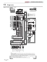
Electrical
The Combi specific electrical circuits are pre-wired from the
factory and no field wiring is required. The tank sensor and
tank thermostat connections on the low voltage connection
board are the inputs for the DHW outlet water sensor and
DHW flow switch, respectively. The DHW pump is pre-wired
to the boiler’s DHW pump output, reference
Table 13-2A -
Inlet Water/System/DHW Sensor Resistance vs. Temperature
Table
on page 71 of this manual.
CAUTION
Specifications


