background image

16

WALL - SMALL - STYLE

EN

11.3 

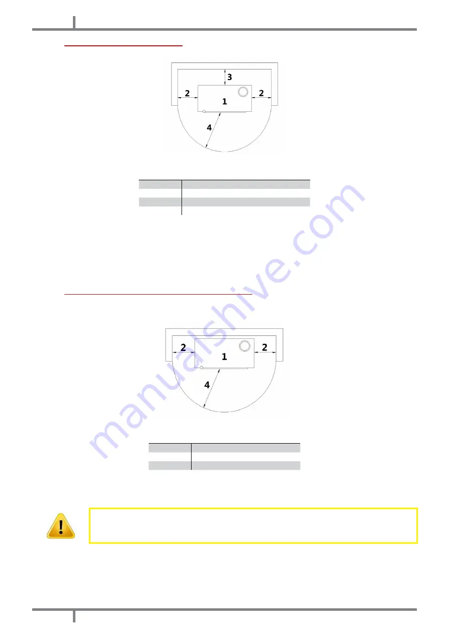
GENERAL INSTALLATION

Fig. 14 - General installation

LEGEND

Fig. 14 page 16

1

Stove

2

Minimum lateral distance = 300 mm

3

Minimum rear distance = 200 mm

4

Minimum front distance = 1000 mm

• 

It is obligatory to install the stove away from walls and/or pieces of furniture, with a minimum air flow of 300 

mm on the sides and 200 mm on the back, to enable an eficient appliance cooling and a good distribution 

of heat in the room (see 

Fig. 14 page 16

).

• 

If the walls are made up of flammable materials, check the safety distances (see 

Fig. 14 page 16

).

• 

At maximum power check that the wall temperature does not ever exceed 80°C. If it would be necessary 

please install a fire resistant plate on the concerned walls.

• 

In some countries also masonring load-bearing walls are considered flammable.

11.4 

WALL MOUNTING (WALL-SMALL MODELS)

The stove is suitable for wall mounting. The  can be attached to a load-bearing wall in masonry (NOT plasterboard, 

wood, etc...) suitable for the entire weight of the stove.

Fig. 15 - Wall mounting

LEGEND

Fig. 15 page 16

1

Stove

2

Minimum lateral distance = 300 mm

3

Minimum front distance = 1000 mm

• 

It is obligatory to install the stove away from walls and/or pieces of furniture, with a minimum air flow of 300 

mm on the sides to enable an eficient appliance cooling and a good distribution of heat in the room (see 

Fig. 15 page 16

).

In some countries also masonring load-bearing walls are considered flammable.

If you want to fix the stove to a non-flammable material wall, you need to fix the support to the wall (the support 

is provided with the stove).

• 

Call an expert to prepare the fumes outlet hole and the combustion air inlet hole.

• 

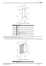
To fix the rear support to the wall with metal plugs su1itable for the weight of the stove (see 

Fig. 16 page 17

).

Summary of Contents for WALL 9 kW

Page 1: ...2015 CADEL srl All rights reserved tutti i diritti riservati en PELLET STOVE installation use and maintenance manual nl PELLETKACHEL handleiding voor installatie gebruik en onderhoud wall small style...

Page 2: ...USE 21 12 1 INTRODUCTION 21 12 2 CONTROL PANEL 21 12 3 USER MENU 22 12 4 START UP 23 12 5 STOVE ADJUSTMENT 23 12 6 FAILED IGNITION 23 12 7 POWER FAILURE 24 12 8 TEMPERATURE SETTING 24 12 9 FUME TEMPE...

Page 3: ...tension Dir 2004 108 EC for Electromagnetic compatibility Read carefully the instruction contained in this manual to obtain the best efficiency This instruction manual is an integral part of the produ...

Page 4: ...th the fume exhaust pipe and nor with every other part of the stove The user or whoever is operating the product must read and fully understand the contents of this installation and use guide before p...

Page 5: ...e observed and therefore the product is used correctly The replacement of the entire system or the repair of one of its components does not extend the guarantee period and the original expiry date rem...

Page 6: ...life the product must not be disposed of as urban waste It must be taken to a special differentiated waste collection centre set up by the local authorities or to a retailer that provides this service...

Page 7: ...ntained with a perfect efficiency The chimney flue must be sole see Fig 1 page 7 with insulated stainless steel pipes 1 or installed on the existing chimney flue 2 Both this solutions must be endowed...

Page 8: ...system must be placed on the roof The chimney flue must be provided CE in accordance with EN 1443 regulation Please find attached an example of label Fig 3 Example of label 9 4 HEIGHT DEPRESSION The...

Page 9: ...2 page 7 9 7 CHIMNEY COMPONENTS Fig 5 Chimney components LEGEND Fig 5 page 9 1 Chimney pot 2 Fume outlet 3 Chimney flue 4 Termal insulation 5 External wall 6 Chimney union 7 Fume pipe 8 Heat generator...

Page 10: ...3 mt 3 3 Sectional view 4 Shield grid 5 Curve inlet to turn downwards For products with a rated power of less than 6 kW it is not advisable to draw the combustion air from outside through direct conn...

Page 11: ...s 3 3 Level section minimum inclination 3 2 mt 2 mt Installation at a height above 1200 m a s l NO Obligatory Use a plate pipe for stoves of 80 mm or 100 mm depending on the type of system and with si...

Page 12: ...ce 0 5 mt Chimney flue installation 100 120 mm with an enlarged drilling for pipe transit Fig 10 Example 2 LEGEND Fig 10 page 12 1 Insulating material 2 Inspection plug 3 Chimney inspection entrance 4...

Page 13: ...egulation EN14961 2 type ENplus A1 Not adequate pellets cause a bad combustion a frequent burning pot obstruction and exhaust conduits obstruction Further it decreases the calorific value soils the gl...

Page 14: ...he fume passage all has been executed in safety probable fume losses and distances from flammable materials etc The installation of the appliance must enable an easy access for appliance fume exhaust...

Page 15: ...le LEGEND Fig 13 page 15 1 Hole combustion air inlet from indoor environment d 4 cm 2 Hole combustion air inlet from outdoor environment d 4 cm 3 Exhaust fumes d 8 cm 4 Hot air outlet d 8 cm 5 94 5 cm...

Page 16: ...dered flammable 11 4 WALL MOUNTING WALL SMALL MODELS The stove is suitable for wall mounting The can be attached to a load bearing wall in masonry NOT plasterboard wood etc suitable for the entire wei...

Page 17: ...Metal plugs If the stove is to be fixed to an inflammable wall it is compulsory to attach further support to the wall cod 5013016 the suppurt is NOT provided with the stove Call an expert to prepare...

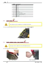
Page 18: ...hole d 120 mm 14 Metal plugs 15 M8x20 bolt 11 5 SAFETY FIXING The appliance must be installed by an authorized technician To avoid accidental tipping fix the stove to the wall with two plugs see Fig 1...

Page 19: ...nstalled by an authorized technician The electric connection occurs through a cable with plug put in an electric socket which is able to support charge and tension specific of every model as described...

Page 20: ...N The stove is endowed with a ventilation system The air blown from fans keeps the appliance at a low temperature range in order to avoid high stresses to the materials which make it up Do not cover t...

Page 21: ...bjected to alterations This occurrence can be attributed to different reasons an excessive stove overheating the presence of chemical agents in bad quality pellets bad chimney draught etc Therefore va...

Page 22: ...r controlling To let them slide press P5 and P6 keys They are POS REFERENCE DESCRIPTION 1 SET CLOCK Set date and time The board is provided with a lithium battery which enables a clock autonomy of 3 5...

Page 23: ...t enter the WORK phase showing the set calorific power and ambient temperature It is in this phase that P5 and P6 keys settle the stove power from 1 to 5 If the value of the ambient temperature exceed...

Page 24: ...Press P3 key and then P5 key till the menu SET CHRONO Press once P3 key and with P5 and P6 keys select the PROGRAM DAY Press once P3 till finding CHRONO DAY With P1 and P2 keys put in OFF or ON It is...

Page 25: ...ON or OFF Press P5 the display shows SUNDAY PROG 1 with P1 and P2 keys set ON or OFF Now press P5 and repeat all the previous instructions for Prog 2 Prog 3 Prog 4 To exit press three times P4 12 15 P...

Page 26: ...y shows ACTIVE ALARM AL 3 HOT EXHAUST and the stove start the switching off phase up Reset the error with P4 key The stove carries out the phase FINAL CLEANING and the is in OFF Check the type of glit...

Page 27: ...ompliance with local regulations with the instructions of the manufacturer and those of your insurance company If there are no local regulations and no instruction from your insurance company it is ne...

Page 28: ...olured if it is weak or if black smoke creates in the inner in this case the burning pot is encrusted and needs to be cleaned If it is broken it must be replaced 14 3 HOPPER AND AUGER CLEANING Per eac...

Page 29: ...placement by an Authorized Technician 14 5 FUME CONDUIT CLEANING The exhaust system must be cleaned every month Fig 45 Fume conduit cleaning Remove the inspection lid of the T union see Fig 45 page 29...

Page 30: ...30 14 8 FUME PIPES ANNUAL CLEANING Clean once a week from soot with brushes The cleaning operation must be executed by a specialized stove repairer who will provide for the cleaning of fume pipe chimn...

Page 31: ...f the fire door is able to stand till 700 C but not to thermal shocks The probable cleaning with usual sale product for glass cleaning must be effected at cool glass in order to avoid explosions You s...

Page 32: ...id of the fume fan Have the fume fan replaced immediately It can be noxious to health to let the stove running without fume fan AL 5 FAILED IGNITION Empty hopper Fill the hopper The burning pot has no...

Page 33: ...ho executes a check from the exhaust up to the chimney pot Fume fan out of order The pellet can burn also thanks to the chimney flue depression without the aid of the fan Have the fume fan immediately...

Page 34: ...es not switch on The stove is without power supply Check if the plug is connected Burned protection fuse in the electric socket Replace the protection fuses in the electric socket 3 15A 250V Faulty co...

Page 35: ...y obsturcted Contact an expert stove repairer who checks the stove from the exhaust up to the chimney pot Provide immediately for stove cleaning Obstructed stove Provide immediately at the inner clean...

Page 36: ...der of the stove extract the fuses to change with the aid of a screwdriver in the shutter see Fig 50 page 36 Fig 50 Shutter with the fuse to remove Proceed as follows Remove the letf panel and you can...

Page 37: ...mg Nm3 24 mg Nm3 24 mg Nm3 Medium POWDER CONTENTS at 13 O2 Max 2 mg Nm3 2 mg Nm3 2 mg Nm3 CHIMNEY DEPRESSION Min Max 10 11 Pa 10 11 Pa 10 11 Pa MINIMUM SAFETY DISTANCE from flammable materials 30 cm...

Page 38: ...RUIK 58 12 1 INLEIDING 58 12 2 BEDIENINGSPANEEL 58 12 3 GEBRUIKERSMENU 59 12 4 STARTEN 60 12 5 INSTELLING KACHEL 60 12 6 GEEN ONTSTEKING 60 12 7 GEEN ENERGIE 61 12 8 SET TEMPERATUUR 61 12 9 TEMPERATUU...

Page 39: ...handleiding staan met aandacht om de beste prestaties te verkrijgen Deze handleiding met instructies maakt integraal deel uit van het product controleer of de handleiding zich altijd bij het apparaat...

Page 40: ...ften op het gebied van de brandpreventie moeten de afstanden ten opzichte van ontvlambare of hittegevoelige objecten in acht genomen worden banken meubels houten bekleding enz Bij zeer ontvlambare obj...

Page 41: ...geeft garantie op het product met uitzondering van de elementen onderhevig aan normale slijtage zoals hierna vermeld gedurende 2 twee jaar vanaf de datum van aankoop wat wordt aangetoond door een bewi...

Page 42: ...zijn voor de uit te voeren werken Bovendien worden de kosten nodig om foutieve technische interventies uitgevoerd door de gebruiker te corrigeren om forceringen te herstellen of alle andere schadelij...

Page 43: ...in samenwerking met Assocosma www assocosma org en is gebaseerd op de Europese normen EN 15287 EN 13384 EN 1856 EN 1443 en UNI 10683 2012 Het hoofdstuk verstrekt aanwijzingen over de goede en correcte...

Page 44: ...e aangrenzende ruimte Onder de opening moet een opvangruimte voor vast materiaal en condens aanwezig zijn die via het metalen hermetisch gesloten deurtje toegankelijk is Extra afzuigsystemen mogen noc...

Page 45: ...grijke functie voor de goede werking van de verwarmingsapparatuur Er wordt geadviseerd een windbestendige schoorsteenpot te gebruiken zie Fig 4 op pag 45 De zone van de gaten voor de afvoer van de roo...

Page 46: ...totaal een minimum netto oppervlak van 80 cm2 hebben genoemd oppervlak moet vergroot worden als er andere actieve generatoren in het vertrek aanwezig zijn bijvoorbeeld een elektroventilator voor de e...

Page 47: ...icht te controleren of alle leidingen volgens de regels van het vak tot stand gekomen zijn volgens de normen EN 1856 1 EN 1856 2 en UNI TS 11278 inzake de keuze van de materialen Het geheel moet in ie...

Page 48: ...h op een afstand van minstens 500 mm van ontvlambare constructie elementen of hittegevoelige elementen bevinden 9 11 VOORBEELDEN VAN CORRECTE INSTALLATIE Fig 9 Voorbeeld 1 LEGENDA Fig 9 op pag 48 1 Is...

Page 49: ...afstand 0 5 m Extern rookkanaal dat tot stand gebracht is met uitsluitend ge soleerde inox buizen dus met dubbele wand minimaal 100 120 mm Het geheel is goed aan de muur verankerd Met windbestendige s...

Page 50: ...e onderdelen die de pelletstroom regelen transportschroef kleine verschillen in het gebruikte materiaal aanwezig zijn zoals ruwheid en porositeit die natuurlijke afwijkingen van de toevoer van de bran...

Page 51: ...rbrandingslucht uit binnenomgeving d 4 cm 2 Inlaat verbrandingslucht uit buitenomgeving d 4 cm 3 Rookgasafvoer d 8 cm 4 Uitlaat warme lucht d 8 cm 5 96 cm 6 87 5 cm 7 15 5 cm 8 26 cm 9 80 cm 10 7 3 cm...

Page 52: ...geving d 4 cm 2 Inlaat verbrandingslucht uit buitenomgeving d 4 cm 3 Rookgasafvoer d 8 cm 4 Uitlaat warme lucht d 8 cm 5 94 5 cm 6 98 5 cm 7 27 cm 8 80 5 cm 9 17 cm 10 17 cm 11 7 3 cm 12 88 cm 13 85 c...

Page 53: ...n muur ge nstalleerd te worden Er wordt op gewezen dat de muur een gemetselde draagmuur moet zijn GEEN gipsplaat hout enz die geschikt is om het gewicht van de gehele kachel te verdragen Fig 15 Instal...

Page 54: ...gen een draagmuur van niet ontvlambaar materiaal wilt installeren moet de houder aan de muur bevestigd worden plus een afstandhouder cod 5013016 de afstandhouder wordt NIET bij de kachel geleverd Neem...

Page 55: ...5 VEILIGHEIDSBEVESTIGING Het apparaat moet door een erkende technicus worden ge nstalleerd Om kantelgevaar te vermijden moet de kachel met 2 pluggen aan de muur worden bevestigd zoals aangeduid op de...

Page 56: ...e nstalleerd worden De elektrische aansluiting vindt plaats met een kabel met stekker op een elektrisch stopcontact dat geschikt is om de lading en de specifieke spanning van ieder afzonderlijk model...

Page 57: ...luchtdiedoordeventilatorenaangeduwdwordt handhaafthetapparaatopeenlaagtemperatuursregime zodat een overmatige belasting op het materiaal waaruit de kachel bestaat vermeden wordt Sluit de openingen voo...

Page 58: ...oorzaken worden toegeschreven overmatige oververhitting van de kachel chemische stoffen die in minderwaardige pellets aanwezig zijn slechte trek van de schoorsteen enz Bijgevolg kan de hechting van d...

Page 59: ...ers Druk op de toetsen P5 en P6 om deze langs te lopen We hebben POS VERWIJST NAAR BESCHRIJVING 1 SET KLOK Stelt de datum en de tijd in De kaart is uitgerust met een lithiumbatterij die de klok een au...

Page 60: ...oldoende hoog is na circa 7 10 minuten kan men de inschakeling als voltooid beschouwen en verschijnt VLAM AANWEZIG op het display Na be indiging van de fase VLAM AANWEZIG neemt de regeleenheid de ARBE...

Page 61: ...selecteer met toetsen P1 en P2 de dag van de week maandag dinsdag woensdag donderdag vrijdag zaterdag en zondag Druk een tweede keer op toets P3 UREN en stel het uur in met toetsen P1 en P2 Druk een...

Page 62: ...tip van inschakeling in of OFF Druk op P5 nu verschijnt de tekst STOP PROG 1 Voer met toetsen P1 en P2 de waarde van het tijdstip van uitschakeling in of OFF Druk op P5 nu verschijnt de tekst MAANDAG...

Page 63: ...E ROOKG de sonde is beschadigd of afgesloten Verricht een reset van de fout met toets P4 De kachel voert een fase EINDE REINIGIN en OFF uit Controleer het type fout aan de hand van ALARMEN op pag 69 R...

Page 64: ...dee thermostaat onderbreken de elektrische voeding naar de transportschroef Verricht een reset van de fout met toets P4 De kachel voert een fase EINDE REINIGIN en OFF uit Controleer het type fout aan...

Page 65: ...orbeeld op een houten vloer gezet wordt omdat de as in de bak de kool nog heel lang brandend houdt Pas wanneer de as gedoofd is kan ze weggegooid worden bij het organische afval Let op de vlam als dez...

Page 66: ...i de 6 schroeven van het inspectiepaneel los zie Fig 42 op pag 66 Fig 43 Reiniging met flessenwisser Fig 44 Reiniging rookkassenkamer Reinig de kanalen met behulp van een flessenwisser zie Fig 43 op p...

Page 67: ...at de schoepen in onbalans raken en meer geluid maken Gezien het delicate karakter van deze reiniging moet dit gedaan worden door een geautoriseerde technicus Fig 46 Reiniging rookgassenafzuiger fase1...

Page 68: ...op onherstelbare wijze beschadigen 14 11 REINIGING VAN DE MAJOLICA EN STEEN ONDERDELEN Enkele modellen kachel hebben een externe bekleding van majolica o steen Deze zijn ambachtelijk gemaakt en het i...

Page 69: ...rookgassen is afgesloten Voer een revisie van de kachel uit De temperatuursonde van de rookgassen is defect Vervang de rookgassensonde AL 3 WARM ROOKG De rookgassensonde is defect Vervang de rookgasse...

Page 70: ...ermische sonde De elektronische kaart is defect Vervang de elektronische kaart AL 6 GEEN PELLET De voorraadbak is leeg Vul de voorraadbak AL 7 WARMTE VEILIGHE De ketel heeft een te hoge temperatuur La...

Page 71: ...rukschakelaar De elektronische kaart is defect Vervang de elektronische kaart De schoorsteen is te lang Raadpleeg een kachel en schoorsteenspecialist en controleer of de afvoerschoorsteen aan de voors...

Page 72: ...bak is leeg Vul de voorraadbak De transportschroef is geblokkeerd door een onbekend object zoals spijkers Reinig de transportschroef De reductiemotor van de transportschroef is kapot Vervang de reduct...

Page 73: ...fzuiger onmiddellijk vervangen Het kan schadelijk voor de gezondheid zijn om de kachel zonder afzuiger te laten werken De ventilator warmtewisselaar blijft draaien ook al is de kachel afgekoeld De tem...

Page 74: ...delen aansluiting van de silicone buis van de pressostaat de rookzuiger en de kamerventilator Door het rechterpaneel te verwijderen krijgt u toegang tot de volgende onderdelen omgevingssonde reductiem...

Page 75: ...24 mg Nm3 Gemiddeld DEELTJESGEHALTE bij 13 O2 Max 2 mg Nm3 2 mg Nm3 2 mg Nm3 ONDERDRUK SCHOORSTEEN Min Max 10 11 Pa 10 11 Pa 10 11 Pa MINIMUM VEILIGHEIDSAFSTAND van ontvlambaar materiaal 30 cm 30 cm...

Page 76: ...a Lucia di Piave TV ITALY tel 39 0438 738669 fax 39 0438 73343 www cadelsrl com Partner of pellet stoves wood stoves wood cooking stoves thermostoves pellet fireplace inserts pelletkachels houtkachels...

Reviews: