RIVER IDROTECH 18 - 24 - 24H2O
16
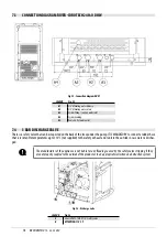
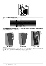
Fig. 30 - Electric socket with master switch
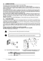
Fig. 31 - Plug connected
• Do not use extension cables.
• If the feeder cable is damaged, it must be replaced by an authorized technician.
• When the stove is not going to be used for a long period of time, it advisable to remove the plug from the socket on the wall.
• An electrical connection to a UPS/ACCUMULATOR/ STABILISER must guarantee a voltage of at least 210 V without power
surges. Considering the variety of UPS on the market regarding size and construction qualities, we cannot guarantee operation
once the stove is connected to these devices.
6.9
STOVE CALIBRATION AND DEPRESSION MEASUREMENT
This stove has a pickup point positioned on the tank in order to measure the depression of the combustion chamber and verify its
proper operation.
To do this, proceed as follows:
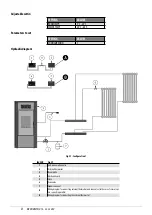
• Connect a digital pressure switch with a tube to detect the negative pressure (see
).
• Load the feed screw via appropriate function.
• Start the stove and set "Set flame" to power 1 (the start-up time of this stove lasts between 8 and 10 minutes to ensure mini-
mum draught).
• Compare the read values with those on the table.
• Change power every 10 minutes and wait for it to stabilise.
• Access the user menu and, if necessary, change the parameters.
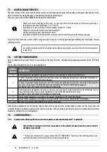
Fig. 32 - Cap removal
Fig. 33 - Digital pressure switch connection
DATA
P1
P2
P3
P4
P5
Stove depression - temperature IDRO
18 kW
20 Pa - 125 °C
30 Pa - 150 °C
42 Pa - 178 °C
54 Pa - 200 °C
65 Pa - 230 °C
Stove depression - temperature IDRO
24 kW
20 Pa - 125 °C
35 Pa - 160 °C
45 Pa - 190 °C
60 Pa - 220 °C
75 Pa - 250 °C
Stove depression - temperature IDRO
24H2O kW
20 Pa - 125 °C
35 Pa - 160 °C
45 Pa - 190 °C
60 Pa - 220 °C
75 Pa - 250 °C
NB: for good combustion, the depression values must be between ± 5 Pa and the temperature values between ± 10°C.


