5. ASSEMBLY INSTRUCTIONS
Ÿ
Note:
The hose and regulator are not supplied. For details contact your local stockist.
Ÿ
I 3B/P (30), I 3+ (28-30/37) and I 3B/P (37),
Appliance categories:
(DK, FI, NO, NL, SE, AT, DE, BE, ES, FR, IE, IT, PT, GB, CH)
On the other end, attach a suitable 30mbar low-pressure
(I3B/P (30) : 30mbar Butane/Propane configurations regulator; I3+(28-30/37): 30mbar Butane
regulator or 37mbar Propane regulator); I3B/P(37): 37mbar Butane/Propane configurations
regulators). Again making sure that the hose is well seated. The type of hose used shall
comply with the relevant EN standard and locate requirement. In South Africa the regulator
used must comply with SABS 1237.
Ÿ
I 3B/P (50)
Appliance category:
(AT, DE)
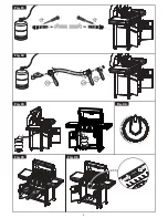
Screw a Hose with the correct threaded fittings on each end, onto the left hand ¼“ BSP
thread of the Valve (O) (Fig.4). Attach a suitable 50mbar low-pressure regulator on the other
end of the hose. The hose used must comply with DIN 4815 part 2 or equivalent.
Ÿ
The hose length should be no less than 800mm and shall not exceed 1.5m.
Check the expiry date on the hose and replace when necessary or when national conditions
require it.
Ÿ
Do not twist or pinch hose. Do not route the hose in any manner that will cause it to come
into contact with any surfaces that would
become hot during use.
Ÿ
Before fitting your gas cylinder
ensure
(Section 7),
that the Valve (M) is in the OFF position by turning
the Control Knob (K) clockwise to
its stop position.
(See Fig.8 a, b)
Ÿ
Fit the Burner Pan(F) onto the Stem(H), and ensure
is sealed properly.(Fig 5)
6. FITTING AND CHANGING THE
GAS CONTAINER
Ÿ
Before fitting the regulator to a gas container, ensure
that the seal on the regulator is in position and in
good condition. This should be done with every connection.
Ÿ
Ensure that the gas container is fitted or changed in a well-ventilated location,
preferably outdoors, away from any source of ignition such as naked flames or
electric fires and away from other people.
Ÿ
Making sure that the gas container is kept upright, screw the regulator onto the
container until it is fully engaged. Hand-tighten only.
Ÿ
If there is a leak on your appliance (smell of gas), take it outside immediately into a
well-ventilated flame-free location where the leak may be detected and stopped.
If you wish to check for leaks on your appliance, do it outside using soapy water
only, which is applied to the joints. The formation of bubbles will indicate the gas
leak.
Ÿ
Check that all the connections are securely fitted and re-check with soapy water.
If you cannot rectify the gas leak,
do not use the appliance.
Contact your
local CADAC stockist for assistance.
Ÿ
When changing a gas container, firstly close the container valve (if fitted) and then
turn the Control Knob (K) clockwise to its stop position. Ensuring that the flame is
extinguished, unscrew the regulator. Refit a full container following the same
precautions as described above.
Fig. 3
Fig. 5
Fig. 4


