INSTALLING THE REPEATER
Page 3-13
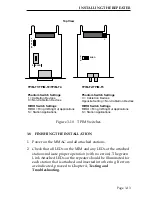
Figure 3-10 TPIM Switches
3.8
FINISHING THE INSTALLATION
1. Power on the MMAC and all attached stations.
2. Check that all LEDs on the MIM and any LEDs at the attached
stations indicate proper operation (with no errors). The green
Link Attached LEDs on the repeater should be illuminated for
each station that is attached and inserted into the ring. If errors
are indicated, proceed to Chapter 4, Testing and
Troubleshooting
.
Top View
TPIM-T1/TPIM-T2/TPIM-T4
Phantom Switch Settings
1 = Cabletron Devices
0 = Non-Cabletron Devices
RI/RO Switch Settings
RI/RO = Ring In/Ring Out Applications
S = Station Applications
TPIM-F2/TPIM-F3
Phantom Switch Settings
C = Cabletron Devices
Opposite Setting = Non-Cabletron Devices
RI/RO Switch Settings
RI/RO = Ring In/Ring Out Applications
S = Station Applications
S
T
N
RI/RO
C
P
H
A
N
T
O
M
0
1
S RI/RO


