background image


ATTACHING THE CONSOLE


Page 2-4


2.2

CONSOLE CABLE CONFIGURATION


A single female DB-9 receptacle provides a Console interface to the 
management terminal. Depending on your specific terminal, one of two 
cable configurations (9 pin to 25 pin or 9 pin to 9 pin) is used for the 
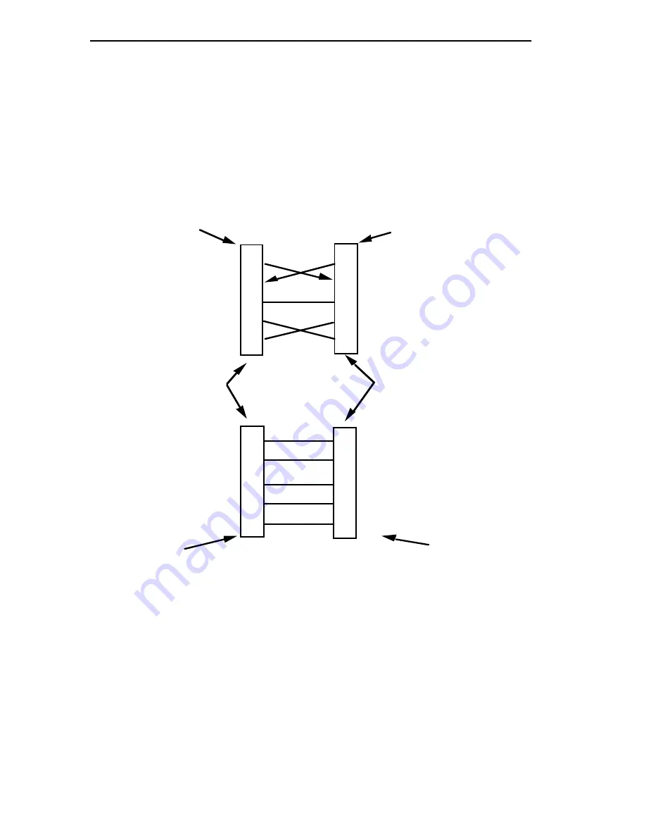
connection to the MRXI Console port. Figure 2-2 shows the pinout for 
both cables.

Figure 2-2. Console Cable Pinouts

Connect the console to the MRXI as follows:

1.

Attach the male 9-pin connector to the CONSOLE port on the rear 
of the MRXI.

2.

Attach the female end (25-pin or 9-pin, as applicable) to the COMM 
port on the terminal.

2

3

5

7

8

CONSOLE PORT

LOCAL MANAGENT

CONSOLE

TRANSMIT

RECEIVE

RECEIVE

TRANSMIT

REQUEST TO SEND

CLEAR TO SEND

SIGNAL GROUND

REQUEST TO SEND

CLEAR TO SEND

SIGNAL GROUND

9 PIN TO 9 PIN

CABLE

MALE - DB-9

(9-Pin Connector)

2

3

5

7

8

2

3

5

7

TRANSMIT

RECEIVE

RECEIVE

TRANSMIT

REQUEST TO SEND

CLEAR TO SEND

SIGNAL GROUND

SIGNAL GROUND

9 PIN TO 25 PIN

CABLE

FEMALE - 25 Pin

 "D" Shell Connector

20

DATA TERMINAL READY

MALE - DB-9

(9-Pin Connector)

FEMALE - DB-9

(9-Pin Connector)


2

3

5

7

8

CLEAR TO SEND

Summary of Contents for MRXI 10BASE-T

Page 1: ...MRXI LM LOCAL MANAGEMENT FOR THE MRXI MRXI 2 ETHERNET 10BASE T HUB USER S GUIDE CABLETRON SYSTEMS P O Box 5005 Rochester NH 03867 0505...

Page 2: ...CIAL OR CONSEQUENTIAL DAMAGES WHATSOEVER INCLUDING BUT NOT LIMITED TO LOST PROFITS ARISING OUT OF OR RELATED TO THIS MANUAL OR THE INFORMATION CONTAINED IN IT EVEN IF CABLETRON SYSTEMS HAS BEEN ADVISE...

Page 3: ...tial area is likely to cause interference in which case the user will be required at his own expense to correct the interference If this equipment does cause interference to radio or television which...

Page 4: ...Console Cable Configuration 2 3 CHAPTER 3 GETTING STARTED 3 1 Using The Management Keyboard 3 1 3 2 Understanding The Screens And Commands 3 2 3 3 MRXI LM Screens 3 2 3 4 Accessing Local Management vi...

Page 5: ...CONTENTS iv...

Page 6: ...n understanding of the features and capabilities of MRXI LM A general working knowledge of Ethernet networks and the IEEE 802 3 standard is necessary for interpreting and using MRXI LM Chapter 1 Intro...

Page 7: ...E MRXI LM The MRXI LM is a menu driven integrated network management tool that permits management and control of the MRXI MRXI LM can be used to Display current MRXI status and statistics for the MRXI...

Page 8: ...report file for future reference For more information on using Remote LANVIEW Windows with the MRXI consult the Cabletron Systems Remote LANVIEW Windows User Manuals or call Cabletron Systems at 603...

Page 9: ...INTRODUCTION Page 1 4...

Page 10: ...he console connection supports a Digital Equipment Corporation VT200 or VT300 series terminal or PC emulation of one of these terminals Figure 2 1 Management Console Connection Table 2 1 lists the set...

Page 11: ...ATTACHING THE CONSOLE Page 2 2 Table 2 1 Terminal Setup Requirements...

Page 12: ...tup Transmit Transmit 9600 Receive Receive Transmit XOFF any option Bits Parity 8 Bits No Parity Stop Bit 1 Stop Bit Local Echo No Local Echo Port EIA Port Data Leads Only VT220 EIA Port Data Leads on...

Page 13: ...he male 9 pin connector to the CONSOLE port on the rear of the MRXI 2 Attach the female end 25 pin or 9 pin as applicable to the COMM port on the terminal 2 3 5 7 8 CONSOLE PORT LOCAL MANAGENT CONSOLE...

Page 14: ...ATTACHING THE CONSOLE Page 2 5...

Page 15: ...ATTACHING THE CONSOLE Page 2 6...

Page 16: ...enu option or alter a field use the keyboard arrows up down left and right to highlight the desired item Only fields that can be changed can be highlighted Incorrect entries field value exceeded etc a...

Page 17: ...ormat conventions Screen formats are illustrated and each field is described within the text a Field titles for fields that can be altered via the terminal keyboard are shown underlined b When a defau...

Page 18: ...approximately 5 seconds warmup the Password Screen appears see Figure 3 2 3 If you are not using the password feature of MRXI LM or if you have not yet applied your own password press Return If you h...

Page 19: ...mmand MAIN is highlighted If an incorrect or invalid password is entered the password prompt remains on the screen allowing you to enter the correct password 4 Press Return to display the Device Port...

Page 20: ...1991 MAIN Device Port Information Device Name SAVE RESET COUNTERS EXIT Device Port 2 1619586 0 0 MRXI Ethernet Address Set IP Address 00 00 1d 00 05 48 34 141 3 14 Packets Receive Collisions Transmit...

Page 21: ...XI end Modem end Pin 2 Transmit to Pin 2 Transmit Pin 3 Receive to Pin 3 Receive Pin 5 Ground to Pin 7 Ground Pin 7 Request to Send to Pin 20 Data Terminal Ready Pin 8 Clear to Send to Pin 8 Data Carr...

Page 22: ...ll the modem The Password Screen is displayed when the connection is established 5 Enter the Password Any Superuser password assigned at the Community Names Screen is valid 6 Press Return The MRXI SNM...

Page 23: ...GETTING STARTED Page 3 8...

Page 24: ...om the local management session and provides access to the Community Names screen Figure 4 1 DEVICE PORT Information Screen The Device Port Information screen presents information related to HUB and t...

Page 25: ...ld and enter the desired IP address as 4 decimal values between 1 and 254 using a period as a separator between values as follows 254 254 254 254 Packets displays the combined count of packets receive...

Page 26: ...led ON the port is enabled OFF the port is disabled Port Segmentation Status shows if the currently selected port is segmented A port is segmented logically disconnected when the MRXI detects 33 conse...

Page 27: ...ently displayed port information and designates the port number used for the ENABLE PORT and DISABLE PORT commands To change the port selection highlight this field and use the plus or minus keys to i...

Page 28: ...e table that lets you designate community names for SNMP compliant network management workstations such as a PC running Remote LANVIEW Windows that can access the MRXI and receive alarms from the MRXI...

Page 29: ...orkstation configured with the associated community name Highlight this field and press Return to toggle between the following possible entries RO Read Only RW Read and Write Access NA Not Accessible...

Page 30: ...screen NOTE Changes to the Community Names Table are not saved by the RETURN command Perform a SAVE if you want to save any changes to the Community Names Table SAVE saves the information currently di...

Page 31: ...USING COMMUNITY NAMES Page 5 4...

Page 32: ...the field length Remedy Check the entry and enter the field again ILLEGAL INFORMATION ENTERED Indicates an attempt to enter inappropriate information i e a non numeric value in a numeric field Remedy...

Page 33: ...MRXI LM MESSAGES Page 6 2...

Page 34: ...password highlight a blank community name field 4 Enter the new password up to 32 characters in length in the Community Name field If you have added a password highlight the associated Access field a...

Page 35: ......

Reviews: