background image

5  |  Description

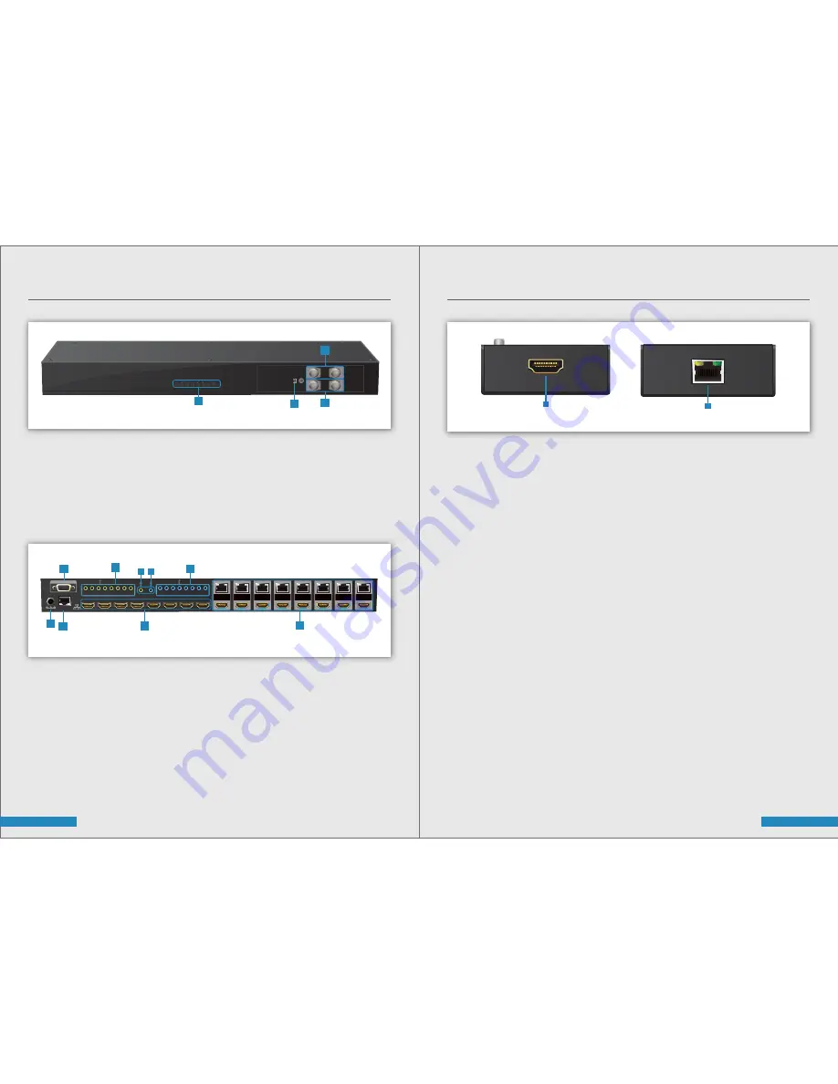
PANEL DESCRIPTIONS FOR TRANSMITTING UNIT 

1. Source Status:

 Input source indicator LED

2. IR Sensor

 IR Sensor for receiving the IR commands from IR Remote

3. Output Push Button & 7-segment LED:

 Front panel push buttons used to select the number of display channel 

& LED display for output ports

4. Input Push Button & 7-segment LED:

 Front panel push buttons used to select the number of input source & 

LED display for input channels

5. +12V DC: 

12V DC power jack

6.  Ethernet:

 Ethernet control port

7. INPUT 1-8: 

HDMI inputs

8. RS-232: 

RS-232 control port

9. IR Receiver 1-8: 

Infrared 3.5mm socket for plugging in the extension cable of IR Receiver

10. System IR Receiver: 

Ext. IR Receiver

11. All IR Output: 

3.5mm IR Blaster socket for HDMI source control on all 8 inputs

12. IR Blaster 1-8: 

3.5mm IR Blaster socket for individual HDMI source control

13. Output Port 1-8:

 RJ-45 & local loop-out HDMI outputs for each output channel

6  |  Description

PANEL DESCRIPTIONS FOR RECEIVING UNIT 

1.


HDMI Output:

 Connect to HDTV with HDMI cable

2. Cat In:

 Plug-in CAT.X cable

Front Panel

Rear Panel

INPUT +

- OUTPUT

- INPUT

4

3

2

1

+ 12V DC

HDMI IN 4

HDMI IN 3

HDMI IN 2

HDMI IN 1

HDMI IN 8

HDMI IN 7

HDMI IN 6

HDMI IN 5

RS-232

OUTPUT 1

OUTPUT 2

OUTPUT 3

OUTPUT 4

OUTPUT 5

OUTPUT 6

OUTPUT 7

OUTPUT 8

Ethernet

SYSTEM

IR Receiver

ALL

IR Blaster

SYSTEM IR Receiver

1

2

3

4

5

6

7

8

1

2

3

4

5

6

7

8

ALL IR Blaster

8

9

12

10 11

5

7

6

13

HDMI OUT

1

CAT IN

2

Summary of Contents for HDelity

Page 1: ...MI IN 5 RS 232 OUTPUT 1 OUTPUT 2 OUTPUT 3 OUTPUT 4 OUTPUT 5 OUTPUT 6 OUTPUT 7 OUTPUT 8 Ethernet SYSTEM IR Receiver ALL IR Blaster SYSTEM IR Receiver 1 2 3 4 5 6 7 8 1 2 3 4 5 6 7 8 ALL IR Blaster H D M I e x t e n d e r o v e r s in g le c a t X w it h b i d ir e c t io n a l IR M in i U S B P o w e r P o w e r In d ic a to r C A T IN HDMI OUT R e c e i v e r IR R e c e iv e r IR B la st e r ...

Page 2: ...rvice this unit yourself except where explained in this manual Provide proper ventilation and air circulation and do not use near water Keep those objects away that might damage the device and assure that the placement of this unit is on a stable surface Use only Power Adapter Power Cords and Connection Cables designed for this unit Do not use liquid or aerosol cleaners to clean this unit Always u...

Page 3: ...our Full 3D HDCP compliant Allows any source to be displayed on multiple displays at the same time Allows any HDMI display to view any HDMI source at any time Supports 7 1 channel Digital Audio Supports default HDMI EDID and learns the EDID of displays Bi Directional IR path The Matrix Master can switch every output channel to any HDMI input by Push in button IR Remote Control RS 232 Control and E...

Page 4: ...ansmitter TX 1x RJ 45 1x IR Socket for IR Receiver N A Receiver RX 8 level digital rotary control HDMI Deep Colour Full 3D Yes Single link 225MHz 6 75Gbps 480i 480p 720p 1080i 1080p60 36 bit Colour Surround sound up to 7 1ch or Stereo Digital Audio Full HD 1080p 35m 115ft CAT X HD 720p 1080i 50m 165ft CAT X 1 Human body model 19kV air gap discharge 12kV contact discharge 2 Core chipset 8kV 5 Volts...

Page 5: ... extension cable of IR Receiver 10 System IR Receiver Ext IR Receiver 11 All IR Output 3 5mm IR Blaster socket for HDMI source control on all 8 inputs 12 IR Blaster 1 8 3 5mm IR Blaster socket for individual HDMI source control 13 Output Port 1 8 RJ 45 local loop out HDMI outputs for each output channel 6 Description PANEL DESCRIPTIONS FOR RECEIVING UNIT 1 HDMI Output Connect to HDTV with HDMI cab...

Page 6: ...x and direct the IR Blaster to point towards the built in IR Receiver of the HDMI source devices 4 Connect the 12V 5A DC power supply to the Cablesson HDelity 5 Power on all HDMI sources Cablesson HDelity MATRIX RECEIVER AS RECEIVER 1 Connect each HDMI output to HDMI displays 2 Connect the CAT X input on the Cablesson HDelity Matrix Receiver to the CAT X output port on the Cablesson HDelity Matrix...

Page 7: ...he LED will blink twice and the mapping setting will be effective D If you push the Output Save button before the mapping setting is effective the LED will show 一 一 to quit the Preset Mapping Mode IR Remote Front OUTPUT INPUT OUTPUT INPUT Preset Learn Save Default tv Cablesson HDElity 8x8 CAT5 6 HDMI Matrix Front View Back View HDMI IN 4 Any HD Source 4 Sky HD HD Source 3 Blue ray Player HD Source...

Page 8: ... button and then the LED will show E L one time to enter Learn Output EDID Mode C Use or output push button to select the output port number D Release Input Default button after selecting the desired output port number and then the LED will blink twice and the setting will be effective E It will quit the Learn Output EDID Mode if you push the input default button before the setting is effective F ...

Page 9: ...LT EDID button 2 Press number key 2 to select default EDID 3 Press TO button 4 Press ALL to select All Input 5 Press TAKE button Default EDID Number Output To All Input Take Operation Ex Learn Output 2 Input 3 Procedure 7 Segment LED Learn Number Output To Number Input Take Learn Output EDID 1 Press LEARN button 2 Press number key 2 to select Output 3 Press TO button 4 Press number key 3 to select...

Page 10: ...us 5 Power ON OFF Button Click this button to ON OFF the power Power ON Status Blue Power OFF Status Red 6 EDID Button A Learn EDID from Default a Select Default EDID 1 8 default EDID b Select Input c Click Learn button to Learn Default EDID 1 Click button to show version information 1 FW SW Version Button 2 COM Port Selection 3 Connection Status 4 Connect Disconnect Button 5 Power On Off Button 6...

Page 11: ...n EDID from Display a Select HDMI Output b Select Input c Click Learn button to Learn Display EDID D Create EDID File a Click Create button to create EDID file b Select the EDID content c Click Save EDID on Computer to save the generated EDID as a file E View EDID File a Select Input HDMI Output or From File b Click View button to read the EDID and Analysis c Click Save As to save the read EDID as...

Page 12: ...the firmware update 8 Network Button A Click Read From Device to read the device IP address B Select Ethernet and then will be a pop up windows C Key in the device IP address to the pop up windows D Close the pop up windows E Click the connected button to connect A Save Mapping a Select mapping 1 8 b Click Save button to save current mapping B Preset Mapping a Select mapping 1 8 b Click Recall but...

Page 13: ...tput the lowest standards in audio format and video resolutions to be commonly acceptable among all HDMI displays In this case a 720p stereo HDMI signal output would be probably the safest choice Nevertheless the user can force the Matrix to learn the EDID of the lowest capable HDMI display among others to make sure all displays are capable to play the HDMI signals normally There are THREE methods...

Page 14: ...le 3 Can every TV work with the HDMI Matrix Basically the answer is YES But if your TV can not support 1080p please refer the EDID LEARNING section to learn EDID from your TV 4 What is EDID Why do I need to learn EDID EDID contains the whole information of the display such as the Resolution and Audio Setting which this display can support Therefore based on the EDID information media player will p...

Page 15: ...duct fail to be in good working order within 1 year warranty period the SELLER at its option will either repair or replace the unit provided that the unit has not been subjected to accident disaster abuse or any unauthorized modifications including static discharge and power surge This warranty is offered by the SELLER for its BUYER with direct transaction only This warranty is void if the warrant...

Reviews: