background image

5. Useful LED combinations

The LEDs for the corresponding pins need to light up to make sure the desired mode is available. Please note 
that  shorted  pins,  diodes,  active  electronics  or  other  faults/things  inside  the  cable  can  provide  false  results. 

Options A and B are for the two possible connector 

I

 orientations and can be inverted by flipping the cable at 

connector 

I

If D+ and D- are connected, they only light up on one side of the tester. This is for compatibility with older USB 
connector generations and can be inverted by flipping connector 

I.


Sources: https://en.wikipedia.org/wiki/USB-C 

https://commons.wikimedia.org/wiki/User:Chindi.ap

A1

A2

A3

A4

A5

A6

A7

A8

A9

A10

A11

A12

B12

B1

B2

B3

B4

B5

B6

B7

B8

B9

B10

B11

RX1+

RX1−

VBUS SBU2

D−

D+

CC2

TX2−

VBUS

TX2+

GND

GND

TX1−

VBUS

CC1

D+

D−

SBU1

RX2−

VBUS

RX2+

TX1+

GND

GND

GND

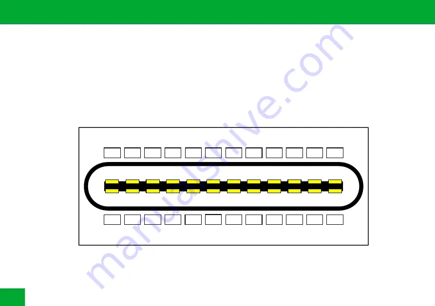
USB C receptable pinout (front view)

6

Summary of Contents for C2C v2.5k

Page 1: ...Manual C2C caberQU v2 5k USB C to USB C cable tester caberqu com...

Page 2: ......

Page 3: ...is not intended to be used by persons including children with restricted sensory physical or mental abilities or lack of experience and or knowledge unless they are supervised by a person responsible...

Page 4: ...Insert a fresh CR2032 battery carefully and fully into the holder The positive contact needs to be on top 3 Device overview Battery CR2032 Connector II USB C Connector I USB C 12x LED 12x LED 1x LED...

Page 5: ...ght up Pins which have a resistor attached in the cable internally will make the corresponding LED light up less intense The cable tester can not detect short circuits in between different pins specia...

Page 6: ...verted by flipping the cable at connector I If D and D are connected they only light up on one side of the tester This is for compatibility with older USB connector generations and can be inverted by...

Page 7: ...Dual lane 3 2 4 Option A VBUS GND TX1 RX1 TX1 RX1 TX2 RX2 TX2 RX2 Shield Debug Accessory Mode Option A VBUS GND D D CC1 SBU1 TX1 RX1 TX1 RX1 Shield Option B VBUS GND D D CC2 SBU2 TX2 RX2 TX2 RX2 Shie...

Page 8: ...6 USB C connector summary USB 2 data Sideband not used for USB Second high speed data USB 3 4 or Alternate Mode Configuration channel plug orientation role detection current mode USB PD communication...

Page 9: ...7 Schematics C2C caberQU 9...

Page 10: ......

Page 11: ...erqu com We as the manufacturer are not liable for damages to persons or property caused by improper installation or operation not described in this manual Any use other than described in this user ma...

Page 12: ...ate from the municipal waste stream via designated collection facilities appointed by the government or the local authorities You avoid environmental damage with the proper disposal Disposal of old el...

Reviews: