16
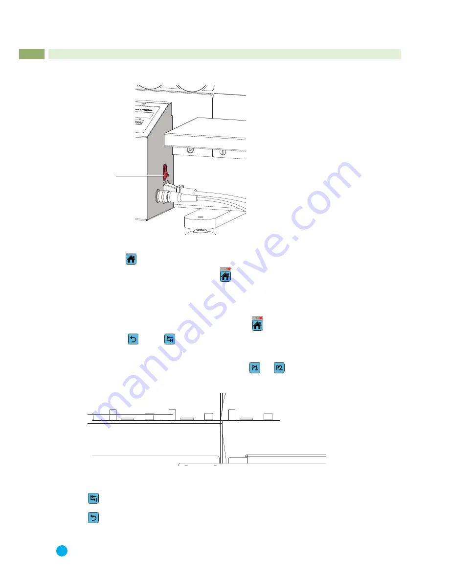
Switch on the device by power switch (1). LED
home
is blinking..
1
Fig. 10
Power Switch
1. Press button
home
.
2. Device will run to the
home
position LED
home
is permanently on.
3. Press the foot-switch and hold it.
- Device will run to the start position (defined by P1) or from the start position short out and back into the start
position.
- Blade synchronization.
4. Deblock the foot switch and the device is ready. LED
home
is permanently on.
5. Choose mode
or mode
.
Chapter 5.10
6. Put in the PCB panel.
Pre-scored groove in the PCB (2) put onto the linear blade (3) and hold the PCB in the horizontal plane by hand.
Ensure that the PCB is positioned within the area between
and
, the pre-selected area of cutting way of
the upper blade.
Chapter 5.7
2
3
Fig. 11
Put on PCB
7. Press the foot-switch to start the program. Foot-switch must be pressed over the length of the program.
Press the foot-switch and hold it. Device performs a cut without return transport of the blade carriage.
Deblock and press the foot-switch again to start the next cut in the reverse direction.
Press the foot-switch and hold it. Device performs a cut with return transport of the blade carriage.
8. Deblock the foot-switch after program end.
i
Notice!
In the mode
F
will be an other start position for the next program start.
6
Operation


