


14
15
Important
• Before installing the operator read these instructions.
• Use of a
HYDRO
product for any application not described in this instruction manual is prohibited.
• The user must be instructed on the use of the automation system.
• The user must be consigned the instruction manual.
• All CAB products are insured against damage or injury caused by manufacturing defects under the essential
condition that the operator has the CE marking and all genuine CAB components are installed.
General Information
Hydraulic operator for swing gates, available in various versions:
HYDRO
reversible – requires an electric lock
HYDRO BA
hydraulic lock on opening stroke – requires an electric lock
HYDRO BC
hydraulic lock on closing stroke
HYDRO BAC
hydraulic lock on opening and closing stroke
HYDRO L
slow version – requires an electric lock
HYDRO PLUS slow version with extended stroke – requires an electric lock.
“Hydro BC” and “Hydro BAC” models are equipped with hydraulic lock on the opening stroke and do not require
an electric lock since the operator locks the wing shut when the motor is not in running.
Models without hydraulic lock on opening stroke (i.e. Hydro - Hydro BA.R - Hydro L - Hydro Plus) always require an
electric lock to guarantee the wing is locked shut mechanically.
All models are equipped with adjustable hydraulic slowdown on the closing stroke.
Preliminary Checks
For the gate automation to work properly, the actual gate must have the following characteristics:
- it must be robust and rigid.
- the hinges must have only limited play and provide smooth and gentle gate movements.
- the whole height of the wings must be in contact when closed.
Gate Stops
If they are not already provided, install gate stops on the opening and closing stroke limits (Fig.3) regardless of the
type of operator being installed.
The closed stop in particular is indispensable given the special characteristics of hydraulic operators. See “maintain
stop” function in the instructions for the control unit.
Installing the automation system
1 Establish the height of the automation from the ground (preferably as close to the centre of the wing as possible
and along a solid cross rail).
Remember that under the operator there is a vent hole and in certain conditions (e.g. rain or snow) it may draw
liquid into the automation. For this reason it is best not to install the operator too close to the ground.
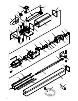
2 Weld or otherwise anchor plate P in place, see installation distances (Fig.2) and the installation diagram (Fig.5):
- remove screws V and cover C
- insert pin P in bracket P as in the figure
- lock everything in place by washer R and self-locking nut D
-
remove the vent plug VS with its gasket RS
. (see note “Vent plug”)
Observe the distances given in the tables at fig. 2, correcting the length of the plate if necessary. In some cases
a recess may have to be made in the post.
It is essential that the installation distances are respected for the operator to work correctly.
With reference to the installation tables note that:
For the wing to open 90°:
A+B must be equal to the operator stroke
For the wing to open more than 90°:
A+B must be less than the operator stroke.
Keep the length differences within 40mm. Over this difference the wing movement becomes uneven. When reduc-
ing lengths A and B , increase the wing speed.
Comply with all statutory regulations.
3 Release the operator (see section “manual gate operation”)
4 Slide out the ram shaft completely and then slide back in by approx. 10 mm. Lock the operator in place.
Always leave a safety overrun of 10 mm in both the closing and opening strokes. The stroke length given in the
technical data and installation tables has already been reduced by the necessary 20 mm.
Summary of Contents for HYDRO
Page 36: ...CL8542500 Rev 07 05 00 ...


