F - Français
Assurez-vous que vous avez supprimé la tension avant l'installation ou
l'entretien. Suivez les procédures d'installation pour assurer le bon
fonctionnement de cette unité. Le produit ne doit pas être modifié, tout
changement entraînera l'annulation de l'agrément de sécurité et le
produit sera rendu dangereux. Le fabricant décline toute responsabilité
sur les produits en cours de modification ou incorrectement installé.
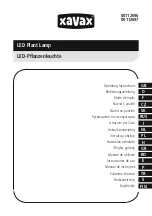
Fig. 1a) Insérer le manchon réversible sur le poteau ou sur la console
murale, et serrer les deux vis de côté le maintenir.
Fig. 1b) Insérer le corps de l’appareil sur le manchon, s'assurer d’un
bon serrage avec les deux vis latérlaes.
Fig. 2) Ajuster l’inclinaison (positions 0, 5, 10 et 15 degrés) au moyen
de la vis supérieure.
Fig. 3) Insérer le câble d'alimentation à l'intérieur de l’appareil au
travers du presse étoupe et serrer avec le couple comme indiqué.
Fig. 4) Connectez les fils au bornier en respectant les polarités.
Fig. 5) Pour accéder au compartiment de câblage:
5a) Dévisser la vis de sécurité, désengager et soulever le couvercle.
5b) Dévissez la vis de sécurité et de soulever le couvercle.
Fig. 6) Pour accéder au compartiment appareillage, pivoter le crochet
de fermeture.
Fig. 7) Pour le remplacement des lampes, désengager le crochet de
fermeture extérieur , et basculer le verre. Pour fermer l'unité suivre la
même procédure dans l'ordre inverse.
Avantgarde
Foglio Istruzione/Instruction Sheet
FI 10/Rev. E - 01/2012
FIS5000.000 - MADE IN ITALY
SHP-T 1x70W E27 1x100/150/250W E40
MH-T/S 1x70/100/150W E27
GB - English
Make sure you have removed tension before installation or
maintenance. Follow the installation procedures to ensure the unit
proper functioning. The product must not be modified, any change will
void security approvals and will make the item dangerous. The
manufacturer declines all responsibility on products being modified or
not correctly installed.
Pic. 1a) Insert the hub on pole or on the arm and tighten the two side
screws maintaining it.
Pic. 1b) Insert the main body on the hub and assure it by tightening
the two side screws.
Pic. 2) Choose the desired angle between 0, 5, 10 and 15 degrees
insert the supplied pin in one of the four slots.
Pic. 3) Insert the power cable inside the unit through the cablegland
and hold as shown.
Pic. 4) Connect wires to the terminal block respecting polarities.
Pic. 5) To access the wiring compartment:
5a) Unscrew the security screw, press the retention tab and raise the
lid.
5b) Unscrew the security screw and raise the lid.
Pic. 6) To access the wiring and lamp compartments pull out the
closure hook.
Pic. 7) For lamp replacement pull to the outside the closure hook and
lower the glass. To close the unit follow the same procedure in
viceversa order.
7
3
Morsetto 3 poli 4mm² 450V 32A
EN 60998-1 EN 60998-2-1
3p socket 4mm² 450V 32A
EN 60998-1 EN 60998-2-1
1a
Avantgarde C/S
Avantgarde Pro
Sezionatore 2 poli 4mm² 400V 16A
EN 60598
2p socket insulator block 4mm² 400V 16A
EN 60598
Avantgarde C/S
Avantgarde Pro
1b
4a
4b
5a
5b
Posizioni lampada/Lamp positions
MH-T, SHP-T, MH-T PH, MV 250W
Pos. 2
SHP-E 150W
Pos. 3
MH-T, SHP-T 100/150W, MH-T
Pos. 4
SHP-E 100W
Pos. 5
MH-E, MH-T, SHP-T, SHP-E 70W, MH-E 100/150W, MV 80/125W
Pos. 6
1
2
I - Italiano
Assicurarsi di aver tolto tensione prima di procedere all’installazione o
alla manutenzione. Seguire attentamente le istruzioni di montaggio per
garantire un corretto funzionamento dell’apparecchio. Il prodotto non
deve essere modificato, qualsiasi modifica annulla le approvazioni di
sicurezza e può rendere pericolosa l’apparecchiatura. Il costruttore
declina ogni responsabilità su prodotti modificati o non installati
correttamente.
Fig. 1a) Inserire il mozzo sul palo o al braccio e stringere le due viti
laterali per assicurarlo.
Fig. 1b) Inserire il corpo principale sul mozzo e assicurarlo stringendo
le due viti laterali.
Fig. 2) Scegliere l’inclinazione desiderata tra 0, 5, 10 e 15 gradi
inserendo il perno fornito in dotazione in una delle quattro cave.
Fig. 3) Inserire il cavo di alimentazione all’interno del prodotto
attraverso il pressacavo e stringerlo come indicato in figura.
Fig. 4) Collegare i conduttori al morsetto rispettando le polarità.
Fig. 5) Per accedere al vano cablaggio:
5a) Svitare la vite di sicurezza, premere sulla linguetta di ritenzione e
sollevare il coperchio.
5b) Svitare la vite di sicurezza e sollevare il coperchio.
Fig. 6) Per accedere al vano cablaggio e al vano lampada tirare verso
l’esterno il gancio di chiusura.
Fig. 7) Per il ricambio lampada tirare verso l’esterno il gancio di
chiusura e abbassare il vetro. Per la chiusura eseguire la stessa
procedura in ordine inverso.
Forza serraggio 7 Nm
Clamping force on cablegland 7 Nm
Couple de serrage du PE 7 Nm
Klemmkraft 7 Nm
Fuerza apriete 7Nm
Siła dokręcenia dławicy 7 Nm
Допустимая нагрузка на ввод 7 Nm
Força de aperto: 7 Nm
C Luce Srl
Via Marmolada, 5/11
20060 Truccazzano - MI - ITALY
Tel +39 02 944 35 095
Fax +39 02 944 35 096
www.cluce.it - [email protected]
2
Avantgarde Plus
6
266
153.
9
Avantgarde Plus
574.5
198.
9
Avantgarde S - IP23
Avantgarde C & Pro- IP65
Avantgarde Plus - IP66
EN605981 IV, 230V 50Hz