


C&K Securitech
3
Mounting
A
Remove the lid screws and remove lid.
B
Unplug any cables connected to the PCB
C
Remove the PCB.
D
Place the panel in the selected position and mark the three fixing holes.
E
Mount the Panel securely using all three positions.
F
Replace PCB and reconnect all cabling.
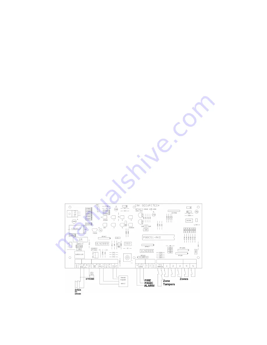
WIRING THE CONTROL PANEL
1 Mains connection
Mains connection should be made through the entry point located towards the
bottom of the panel and the cable must be separate to all other wiring. The cable
MUST be earthed and we recommend power is taken from a 3 Amp fused spur
and wired by a qualified electrician.
2 Battery connection.
The Active 5 requires a standby battery to be fitted to provide power in the event
of mains failure. A sealed lead acid battery should be fitted (maximum 6 Ah).
3 Detector circuits
Connections are provided for up to five detector circuits on which normally
closed detection devices should be used. One or more devices may be
connected to each alarm circuit. These should be connected in series. The
circuit connections are located to the bottom right of the PCB.


