- 6 -
Install resistors R10 – R13 (1K, brn-blk-red). These
limit the current flowing into LEDs D1 – D4.
Install glass diodes D5 & D6. (1N4148) The black
stripes should be nearest J1. Bend like resistors.
Install glass diode D7. (1N4148) The black stripe
should be nearest LED D1. Bend like resistors.
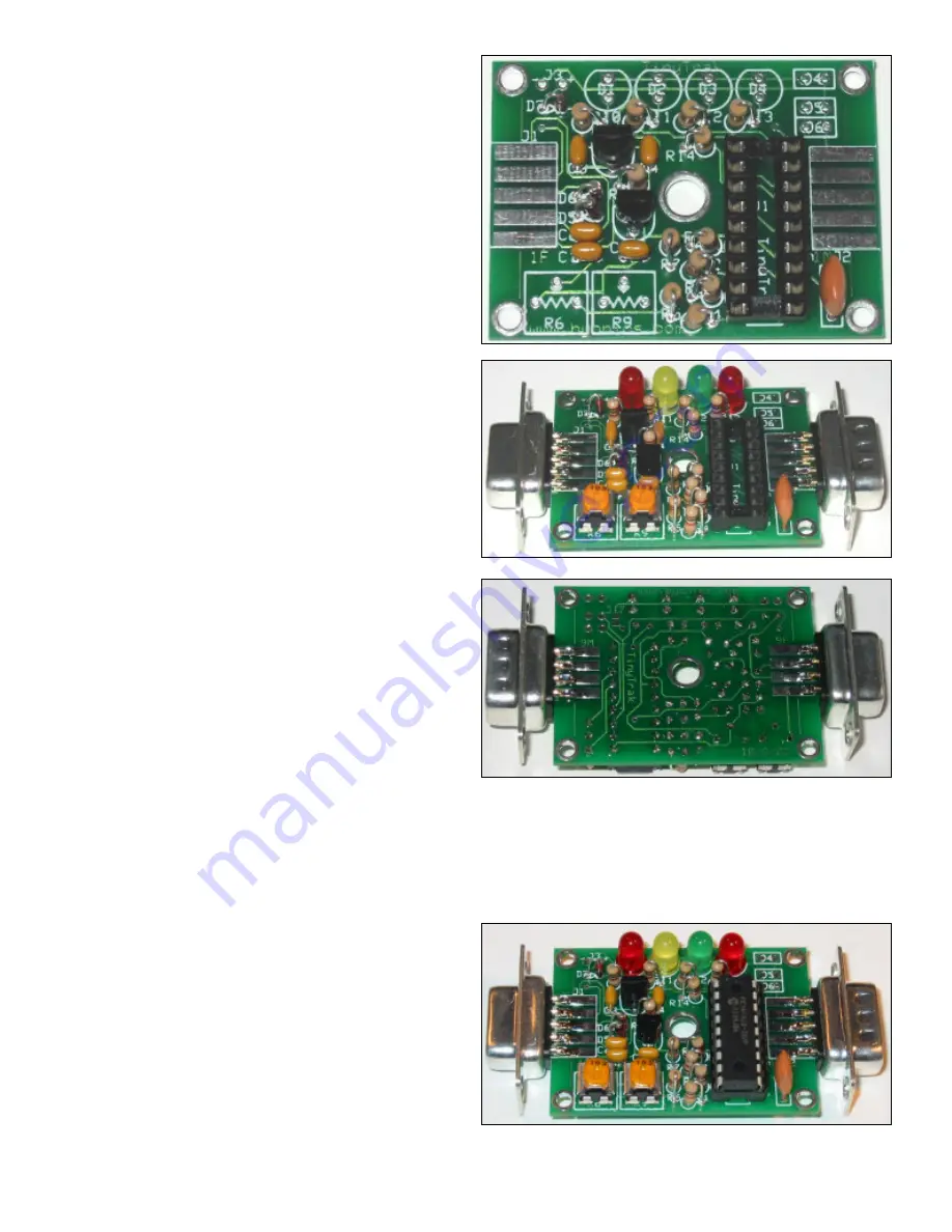
Install potentiometer R6, (10K, 103) which adjusts
audio output level.
Install potentiometer R9, (10K, 103) which adjusts
carrier detect sensitivity.
Install Power Display LED D1 (red). This LED will
light when device is powered. Be sure to align the
flat side of all LEDs with the shape on the silk-
screen, nearest the top edge of the PCB.
Install Carrier Detect LED D2 (yellow). This LED will
light constant when audio is detected from the radio
receiver, and flash during the quiet time before
transmitting.
Install GPS State LED D3 (green). This LED will
light constant when receiving good (locked) GPS
data, and flash when receiving bad (unlocked) GPS
data. It will be off when no GPS data is received.
Install PTT LED D4 (red). This LED will light when
the radio is keyed via PTT.
Install female DB-9 radio connector J1. This is the
connector with the holes. Wedge the board in
between the two rows of solder cups, with the 5
pins aligned with the 5 pads on the PCB. Solder just
one pin first, and insure the connector is on straight.
Then solder on both sides of the PCB, all nine cups
to the pads.
Install male DB-9 serial connector J2 as you did for J1. This is the connector with the pins.
Assembly Completion
After all components have been installed, inspect the solder side of the board for poor or cold solder joints. All pads
should be shiny and smooth. Inspect for any undesired solder bridges. Use an ohmmeter or multimeter to be sure power
(socket pin 14) and ground (socket pin 5) are not connected. It would even be a good idea to power the board (see
below), and c5 volts between socket pins 14 and 5. If the board looks ready, complete the assembly as follows.
Insert programmed microprocessor U1. The chip is
static sensitive, so ground yourself by touching a
large metal object before touching the chip. The
rows of pins may need to be bent slightly. Be sure
to align the notch on the chip with the notch on the
socket, as well as the notch on the silk-screen
(nearest connector J1). An improperly inserted chip
may become permanently damaged. When
powered, the green and yellow LEDs should flash 3
times, which means the TinyTrak3 is running.


