Section 2
– Mockup and Fit Check
JEM Section 2- 3 -
running the Output Jack wiring (…typically blue & black) and the Tremolo ground wire ( …black)
through the respective tunnels (Fig. 2.3).
2.
Carefully move the Pick Guard so that it is flush with the top of the Body, while aligned with the
Neck Pocket and the contours of the body. Mark & pre-drill 2 holes in the Body for mounting
the Pick Guard. Using 3/8” screws (item 3 on Material list), attach the Pick Guard (2 screws).
3.
After ensuring the alignment of the Body & Pick Guard, mark and drill the remaining Pick Guard
holes with a 1/16” drill bit. Ensure all holes are pre-drilled.
2.4
C
h
eck Tremolo C
l
aw Alignment and Fit
Check (item #5 on material list)
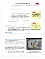
Place the Tremolo claw in the back pocket of the Body
(Fig 2.4) ensuring the claw is centered in the pocket.
1.
In order to make the assembly process easier,
pre-tin the claw ground point (raised tab in the
center of the claw);
2.
Using the claw as a template, mark the hole
positions and pre-drill 2 holes;
3.
Start the mounting screws approximately ½” into
the Body – ensure they are centered (Figure 2.4).
2.5
Fit check of the Tremolo, Jack (Fig 2.5.1)
and Truss Rod Adjustment Cover
2.5.1
Tremolo cover:
1.
Place cover over Tremolo pocket, pearl finish up
(item 12 in material list);
2.
Mark the holes and drill starter holes with 1/16 drill
bit.
2.5.2
Output Jack Cover:
1.
Place cover over Output jack pocket, pearl finish up (item 12 in material list);
2.
Mark the holes and drill starter holes with 1/16 drill bit.
2.5.3
Truss Rod cover:
1.
Place cover over Truss rod access hole (Fig 2.5.3), pearl
finish up (item #14 on material list);
2.
Mark the holes and drill starter holes with 1/16 drill bit.
2.6
Check Strap Pins
1.
Check for pre-drilled holes for the Strap Pins (item 10 on
Figure 2.4 Tremolo claw Alignment
Figure 2.5.1 Back Body Cover Alignment
Figure 2.5.3 Truss Rod cover

