BWT Domestic R.O. System RO300 Installation And Service Manual Download Page 4

1300 720 299

R.O. Unit and Tank Installation

Drain Clamp Installation: 

FIGURE B 

2

3

The R.O. unit is normally mounted to the right or left sink cabinet sidewall, depending on where supply tank is to be 

located. Generally the unit is installed at the front of the cabinet and the tank at the rear.
To mount the unit, elevate it at least 75mm off the floor, level it and mark the location of mounting holes needed. Drill 

hole for mounting screws and install screws allowing the mounting bracket slots to slip over them.
 Locate the tank in a suitable location under the sink.
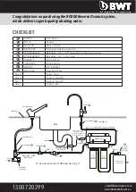
RO300 Tubing

BLUE 3/8” 

From – Product water from R.O. tank  

To – Faucet or point of use

WHITE 1/4” 

From – Cold water supply   

To – Inlet LHS of pre filter to R.O.

YELLOW 1/4” 

Supplied water to and from tank.

BLACK 1/4”   

From – Waste outlet of R.O. membrane 

To – Drain Connection.

A Drain Clamp is used to make a wastewater connection with the drain under the sink, which is designed to fit around 

a standard 1-1/2” OD drainpipe. The drain clamp should always be installed before (above) the p-trap and on a vertical 

or horizontal drain. Do not install the drain clamp near a garbage disposal to avoid clogging the drain line with debris. 

1.

Position the drain clamp at selected location and mark for the opening.

2.

Drill 1/4” hole at mark through one side of pipe.

3.

Position the drain clamp on the drain pipe so the opening aligns with drilled hole. Use a small drill bit to verify that drain 

clamp is properly aligned.

4.

Secure drain clamp firmly onto the drain pipe.

5.

Connect the black drain line of the R.O. into the attached drain clamp assembly.

Drain line

Drain clamp

Use screwdiver

to tighten

Figure B

Upon installation of the RO300, it will take up to one hour 

for the tank to fill and the RO300 drain system to shut off 

(drain flow to stop) 
We recommend draining the first full tank of R.O. water to 

flush the tank and tubing. After this the water will be ready 

for use.

Note:

 If the cabinet sidewalls are not solid, unit may sit on 

the floor with screws used just to keep it against the cabinet 

in a vertical position

Fit the 1/4” ball valve (speedfit) to the top of the tank (use 

Teflon tape). Do not overtighten.

[email protected]     

www.bwtaustralia.com.au

Summary of Contents for Domestic R.O. System RO300

Page 1: ...0 720 299 Installation and Service Guide Domestic R O System RO300 N1UG05 N1IS35 1 2 RO300 Please read this manual carefully before attempting installation sales bwtaustralia com au www bwtaustralia com au ...

Page 2: ... superb quality drinking water Faucet Tap connector Bench top Sink Typical RO300 Installation and Checklist N1IS35 Cold water tap To use quick connect fittings See Fig D See Fig B See Fig C See Fig A 10 6 8 4 3 5 2 9 Drain 1 4 x 1 4 Ball Valve Speedfit Hydro Pneumatic Storage Tank Grey adaptor Water Flow Cold water Stop valve Cold water Inlet S S braided hose Drain Clamp Flow Restrictor Out In Whi...

Page 3: ... 1 Power drill and drill bits 2 Phillips head screwdriver 3 Adjustable wrench 4 Hammer and center punch Installing the Faucet 1 Ensure the faucet location is suitable for your kitchen A 2 diameter foot print is required 2 Mark the centre with centre punch for the 1 4 pilot hole 3 Drill the pilot hole 4 Continue to enlarge hole with larger size drill bit until it is 1 2 12mm 5 Clean up any sharp ed...

Page 4: ...ys be installed before above the p trap and on a vertical or horizontal drain Do not install the drain clamp near a garbage disposal to avoid clogging the drain line with debris 1 Position the drain clamp at selected location and mark for the opening 2 Drill 1 4 hole at mark through one side of pipe 3 Position the drain clamp on the drain pipe so the opening aligns with drilled hole Use a small dr...

Page 5: ...of the cabinets 2 Cut tubing to correct length using tube cutter provided 3 Make sure there are no crimps in the tubing 4 Keep tubing from the R O unit to the tank and faucet as short as possible for good flow 5 Connect blue tube from R O to tap connector or point of use 6 Leave the yellow tube to flow to atmosphere into a small bucket so all air is purged through the system The isolating valve or...

Page 6: ...nsert tube 1 Push up to tube stop 2 Pull to check secure 3 Disconnecting 4 1 Fitting grips before it seals Ensure tube is pushed into the tube stop Push the tube into the fitting to the tube stop The collet gripper has 2 stainless steel teeth which hold the tube firmly in position while the O ring provides a permanent leak proof seal 3 Pull on the tube to check that it is secure It is a good pract...

Reviews: