Art.Nr. 24576_00
Bedienungsanleitung
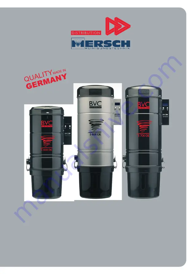
für digitale BVC Zentralstaubsauger C 600 DE , S 600 DE und S 700 DE
BLACKLINE & SILVERLINE
Operation Manual
for digital BVC central vacuum cleaners C 600 DE, S 600 DE and S 700 DE
BVC
Page 1: ...edienungsanleitung für digitale BVC Zentralstaubsauger C 600 DE S 600 DE und S 700 DE BLACKLINE SILVERLINE Operation Manual for digital BVC central vacuum cleaners C 600 DE S 600 DE and S 700 DE BLACKLINE SILVERLINE BVC ...
Page 2: ...icht mit Detailbeschreibungen C 600 DE Seite 8 Rückansicht mit Detailbeschreibungen C 600 DE Seite 9 Wandmontage des Zentralstaubsaugers Seite 10 Stromversorgung Seite 11 Installation des Niedervoltkabels und der Saugrohre Seite 12 Installation des BVC Abluftschalldämpfers Seite 13 Verwendung des HEPA Filters Seite 14 Bedienung der Elektronik Steuerbox Seiten 15 22 Saugrohr Handgriff mit Info LED ...
Page 3: ...oder SchädenanPersonenzuvermeiden iststetsFolgendeszubeachten 1 HaltenSiedieNetzanschlussleitungvonheißenFlächenfern 2 DerBVCZentralstaubsaugeristkeinSpielgerät kannjedochvon Kindernab8JahrensowievonPersonenmitverringertenphysischen sensorischenodermentalenFähigkeitenunterBeaufsichtigungbe nutztwerden wennzuvoreineeingehendeUnterweisungbezüglich dessicherenGebrauchsdesGerätesstattgefundenhat Ebens...
Page 4: ...n BlockierteSaug dosennichtbenutzen HaltenSiedieÖffnungenfreivonStaub Fusseln HaarenundallenDingen diezueinerUndichtigkeitführen unddieSaugkraftbeeinträchtigenkönnen 8 VermeidenSiees mitdenHaaren demGesicht denFingernundmit losenKleidungsstückenindieNähevon Saugöffnungenzukommen 9 SaugenSiekeineglühendenZigaretten heißeAsche brennende StreichhölzeroderähnlicheMaterialienauf Aschesolltenurbei Verwe...
Page 5: ...Steckdose dasichderBVCZentralstaubsaugerimmerimStand by Modusbefindet 17 Esistgrundsätzlichzubeachten dassderAnschlussnuraneiner fachgerechtgeerdetenSteckdoseerfolgendarf Bewahren Sie diese Bedienungsanleitung sorgfältig auf Achtung Wichtig Bei der Inbetriebnahme des BVC Zentralstaubsaugers befindet sich das Gerät sofort im Stand by Modus sobald es am Stromnetz ange steckt ist Die am Gerät befindl...
Page 6: ...rt Nr 21072 POWER Taste Ein Austaste für Dauerbetrieb Kein Hauptschalter MENU Taste Motordeckel Art Nr 12290 Anschluss für Rohrbogen und oder Schalldämpfer Die Abluftöffnung am Motordeckel beträgt 100mm Ø Verstellbare Halteklam mer für Staubbehälter Art Nr 21154 Schmutzbehälter Art Nr 12262 Motorschutzfilter Baumwolle Art Nr 10190 Motorschutzfilter CORDURA Art Nr 29102 Staubfilterbeutel Art Nr 130...
Page 7: ...gen S 600 DE S 700 DE Unterdruckventil Art Nr 12030 Kaltgerätebuchse für Netzanschluss leitung 230 V Anschlussbuchse für Niedervoltkabel Verschlussdeckel für Ansaugflansch silber Art Nr 10210 Ansaugflansch schwarz Art Nr 21150 Montagevorrichtung mit Silentblöcken zwecks Körperschall unterbrechung Anschlussflansch 50mm Ø Art Nr 10226 ...
Page 8: ...r 21072 POWER Taste Ein Austaste für Dauerbetrieb Kein Hauptschalter MENU Taste Motordeckel Art Nr 13094 Anschluss für Rohrbogen und oder Schalldämpfer Die Abluftöffnung am Motordeckel beträgt 100mm Ø Verstellbare Halteklam mer für Staubbehälter Art Nr 21154 Schmutzbehälter Art Nr 13078 Motorschutzfilter Baumwolle Art Nr 13032 Motorschutzfilter CORDURA Art Nr 29100 Staubfilterbeutel Art Nr 13060 H...
Page 9: ... mit Detailbeschreibungen C 600 DE Kaltgerätebuchse für Netzanschluss leitung 230 V Anschlussbuchse für Niedervoltkabel Verschlussdeckel für Ansaugflansch silber Art Nr 10210 Ansaugflansch schwarz Art Nr 21150 Unterdruckventil Art Nr 12030 Anhängevorrichtung für Wandmontage Anschlussflansch 50mm Ø Art Nr 10226 ...
Page 10: ...rung Die Oberkante der Wandhalterung des BVC Zentralstaubsaugers wird ca 130 cm bis 150 cm über dem Boden an der Wand befestigt so dass der Schmutzbehälter bequem entfernt werden kann Wir empfehlen einen Abstand von mindestens 20 cm zur Decke einzuhalten Oberkante der Wandhalterung 130 150 cm 42 cm min 20 cm min 20 cm 130 150 cm 33 cm Decke Fußboden Decke Fußboden Wand Wand ...
Page 11: ...nderen Saugdosen funktionieren automatisch wenn der Saugschlauch einge steckt wird Elektroanschluss Die vor Ort geltenden Bestimmungen sind zu prüfen und die mitgelieferte Netzan schlussleitung ist zu verwenden Diese ist in eine abgesicherte Steckdose mit den fol genden Eigenschaften zu stecken Geräte C 600 DE und S 600 DE 16 Ampere Sicherung Typ B Gerät S700 DE 16 Ampere Sicherung Typ C Anweisung...
Page 12: ...am BVC Zentralstaubsauger zusammen zu fassen Die 5 Volt Steuerleitungen sollten nicht zusammen mit Starkstrom oder mit 230 Volt Leitungen verlegt werden wie es z B bei einem Kabelkanal der Fall wäre Installation des Niedervoltkabels und der Saugrohre S 700 DE 5 Volt Niedervoltkabel Kehrfix zum Staubsauger zum Staubsauger richtig falsch Fall und Steigrohre dürfen nicht in Flucht sondern müssen vers...
Page 13: ...ten Sie dass kein Wasser in die Rohrleitung des Abluftauslasses an der Außenwand gelangen darf Dies kann elektrische Schläge verursachen Schalldämpfer Art Nr 11822 Abluftgitter weiß Art Nr 11804 Abluftgitter Edelstahl Art Nr 11820 Außenwand Saugrohr 5 Volt Steuerleitung Art Nr 10138 Für Abluftleitung 100 mm HT Rohr verwenden 220 240 Volt geerdete Steckdose ...
Page 14: ...er Abluft in den Innenraum Wir empfehlen eine regelmäßige Kontrolle des HEPA Filters und dessen Wechsel bei starker Verschmutzung Einsetzen und Entfernen des HEPA Filters Zum Einsetzen bzw Wechseln des HEPA Filters ziehen sie zunächst den Netzstecker aus der Steckdose Danach lösen Sie die Schrauben am Motordeckel Drehen Sie den Motor deckel um und legen Sie ihn auf eine ebene Unterlage Den HEPA Fi...
Page 15: ...u reduzieren Halten Sie die POWER Taste erneut ge drückt um die Saugleistung wieder zu erhöhen Drücken Sie die POWER Taste nochmals kurz um das Gerät auszuschalten und den Stand by Modus wieder herzustellen Achtung Schalten Sie den BVC Zentralstaubsauger im Alltag immer nur am Saugschlauch ein Ist kein Saugschlauch angeschlossen und wird das Gerät an der Elektronik Steuerbox eingeschal tet fehlt d...
Page 16: ...der Name des Menüs angezeigt damit sie immer informiert sind welche Funktion gerade ausge wählt ist Der Betriebsstundenzähler zeigt die Gesamtbetriebsstunden an Hier wird bei Fehlermeldungen ein Warnzeichen angezeigt Bedienung der Elektronik Steuerbox Das Display Das Display zeigt je nach aufgerufener Funktion unterschiedliche Ansichten und ist stets in vier Bereiche aufgeteilt ...
Page 17: ...l die POWER Taste und halten diese zwei Sekunden gedrückt Bedenken Sie aber bitte dass die Anzeige nur interpoliert ist Werden beispielsweise viele grobe Teile wie Styroporflocken gesaugt kann der Füllstand nicht mehr korrekt berechnet werden BVC empfiehlt den Füllstand des Staubfilterbeutels zusätzlich von Zeit zu Zeit am Sichtfenster des Staubbehälters zu kontrollieren 1 Status Durch längeres Dr...
Page 18: ... Sie einmal kurz die POWER Taste Der Motor fährt auf die höchste Leistungsstufe und erzeugt einen Unterdruck im System Dieser Test dauert 8 Sekunden Je nach dem wie dicht das System aus Rohrleitungen und Saugdosen ist wird der Unterdruck variieren Während der Test läuft können Sie am Ausschlag des Balkendiagramms den Zustand des Rohrsystems erkennen Abhängig vom Wert des Unterdrucks wird die Anzei...
Page 19: ...ches befindet sich eine Tabelle in der für jede Saugdose ein bei diesem Test ermittelter Indexwert vom Monteur Installateur eingetragen sein sollte Ist dies nicht geschehen müssen Sie den Test bei einem einwandfrei dichtem siehe 3 Lecktest und verstopfungsfreien Rohrsystem erneut durchführen siehe Installationshandbuch Verstopfungstest Messadapter Für den Verstopfungstest benötigen Sie den mit Ihr...
Page 20: ...bsauger eine Verstopfung vorliegen die beseitigt werden muss Durch Wiederholung der Messung an anderen Saugdosen lässt sich der verstopfte Rohr strang mit großer Genauigkeit eingrenzen Achtung Für die jeweilige Test phase sollte der BVC Zentralstaubsauger nicht länger als jeweils ca 60 Sekunden im verdichteten Zustand alle Saugdosen sind geschlossen eingeschaltet bleiben um eine unnötige Motorüber...
Page 21: ... funktionie ren so können Sie sich durch Aufrufen des Meldungen Menüs über die Ursache im Klartext informieren Im mittleren Feld des Displays erscheint ein Warnsymbol Durch fünfmaliges Drücken der MENU Taste gelangen Sie in das Mel dungen Menü Ist die Fehlerursache behoben können Sie das Meldungen Menü durch einen Druck auf die POWER Taste zurücksetzen Bedienung der Elektronik Steuerbox ...
Page 22: ...ändern gehen Sie bitte wie folgt vor Bedienung der Elektronik Steuerbox 1 MENU Taste gedrückt halten und 3 x POWER Taste drücken So erreichen Sie das Service Menü 2 MENU Taste drücken um auf Seite 2 zur Sprachauswahl zu gelangen 3 POWER Taste zur Auswahl der Sprache drücken bis die von Ihnen gewünschte Sprache erscheint z B Deutsch 4 Anschließend bringen Sie mit der MENU Taste die Markierung unten...
Page 23: ...eregler am Handgriff aus der OFF Stellung in Richtung Saugrohr Je nach Stand des Potentiometers wird die Sauglei stung stärker oder schwächer geregelt Um Ihnen einen höchstmöglichen Bedienungskomfort zu ermöglichen ist am Handgriff eine Leuchtdiode LED angebracht Sie leuchtet dauerhaft sobald der BVC Zentralstaub sauger gestartet wird Sobald Störungen auftreten oder der Staubfilterbeutel seinen ma...
Page 24: ...lterbeutels ziehen Sie zunächst den Netzstecker aus der Steckdose Anschließend öffnen Sie die seitlichen Halteklammern des Schmutzbehälters und nehmen diesen ab Staubfilterbeutel entfernen Der volle Staubfilterbeutel sollte immer mit beiden Händen am blauen Kunststoff Flansch abgezogen werden Ziehen Sie dabei nicht senkrecht nach unten sondern waagerecht in Richtung des Rohrstutzens siehe Abb 1 Ne...
Page 25: ... der BVC Zentralstaubsauger von der Wand genommen und kopfüber auf eine ebene Fläche gestellt wird Der Federspannring muss an der Lasche zur Mitte hin angezogen werden siehe Abb 1 Hierdurch verformt sich der Motorschutzfilter was zum Entfernen notwendig ist Überprüfen Sie vor dem Einsetzen des neuen Motorschutzfilters den Motorraum auf absolute Staubfreiheit Staubpartikel können den Motor ernsthaf...
Page 26: ...en Verstopfungstest durch wie er auf den Seiten 19 und 20 dieser Bedie nungsanleitung beschrieben ist Führen Sie diesen Test für jede Saugdose durch Für die jeweilige Test phase sollte der BVC Zentralstaubsauger nicht länger als jeweils ca 60 Sekunden im verdichteten Zustand alle Saugdosen sind geschlossen eingeschal tet bleiben um eine unnötige Motorüberlastung zu vermeiden Haben Sie die Verstop ...
Page 27: ...icht liegt ein Defekt am Motor vor Bitte kontaktieren Sie einen BVC Partner oder wenden Sie sich direkt an BVC EBS Distribution GmbH Kontakt siehe unten 3 Wenn die Anzeige an der Elektronik Steuerbox leuchtet ist die Stromversorgung ge währleistet Versuchen Sie den Motor am BVC Zentralstaubsauger mit der POWER Taste für den Dauerbetrieb einzuschalten Startet der Motor liegt das Problem nicht am Mo...
Page 28: ...escription S range page 33 Front view with detailed description Compact 600 DE page 34 Rear view with detailed description Compact 600 DE page 35 Wall mounting page 36 Electrical installation and power supply page 37 Installation of the low voltage cable and suction pipe page 38 Installation of the BVC exhaust air muffler page 39 Usage of the HEPA filter page 40 Operation of the electronic box pag...
Page 29: ...leaning your BVC central vacuum cleaner e g filter change Warning Read the following instructions BEFORE using this appliance to reduce the risk of burns fire electric shock or injuries 1 Keepthepowercordawayfromheatedsurfaces 2 Thisapplianceisnotatoy butcanbeusedbychildrenfrom8yearsup andpersonswithreducedphysical sensoryormentalcapabilitiesor lackofexperienceandknowledge iftheyarebeingsupervised...
Page 30: ...ercordaroundsharpedgesorcorners 6 Neverdisconnectthemainpowerplugbypullingonthepowercord Todisconnectthemainpowercordfromtheoutlet alwaysgraspthe plug neverthepowercord 7 Donotputanyobjectsintotheinletvalves DonotuseyourBVCcen tralvacuumcleanerwheninletvalvesareblocked Keeptheopenings freeofdust lint hairandanythingthatmayreduceairfloworcom promisesealtightness 8 Keephair bodypartsandlooseclothing...
Page 31: ...Ccentralvacuumcleanerfromthemain powersupplyinstand bymode KEEP THIS MANUAL HANDY FOR FUTURE REFERENCE Attention Important When put into service and connected to the mains the BVC central vacuum cleaner is operating in standby mode The POWER button on the unit is intended for testing purposes only The standard posi tion for this button is the stand by mode In order to avoid damage to the motor the...
Page 32: ...or cover art no 12290 connection for pipe elbow and or muffler 100mm diameter exhaust opening on the motor cover fixing clamps for dust container art no 21154 dust container art no 12262 electronic box digital silver art no 21070 electronic box digital black art no 21072 motor protection filter cotton art no 10190 motor protection filter CORDURA art no 29102 filter bag art no 13060 HEPA filter art...
Page 33: ... detailed description S 600 DE S 700 DE vacuum valve art no 12030 connector for voltage wire 230 Volt connector for low voltage wire art no 12176 cover for suction flange silver art no 10210 for suction flange black art no 21150 wall mounting unit with sound absorbing rubber blocks suction flange 50mm Ø art no 10226 ...
Page 34: ...digital black art no 21072 motor cover art no 13094 connection for pipe elbow and or muffler 100mm dia exhaust opening on the motor cover fixing clamps for dust container art no 21154 dust container art no 13078 motor protection filter cotton art no 13032 motor protection filter CORDURA art no 29100 filter bag art no 13060 HEPA filter art nr 12296 POWER button for continuos operation MENU button ...
Page 35: ...eaner Rear view with detailed description Compact 600 DE connector for voltage wire 230 V connector for low vol tage wire art no 12176 cover for suction flange silver art no 10210 for suction flange black art no 21150 vacuum valve art no 12030 wall mounting unit suction flange 50mm Ø art no 10226 ...
Page 36: ...nted at a height of approximately 130 cm to 150 cm measured from the floor for easy removal of the dust container For proper cooling of the motor we suggest a distance of at least 20 cm to the ceiling Wall mounting top of wall mount top of wall mount 130 150 cm 42 cm min 20 cm min 20 cm 130 150 cm 33 cm ceiling floor ceiling floor wall wall ...
Page 37: ...ch on the unit is used only for testing purposes All valves are operating automatically when the hose is plugged The standard position for this button is the stand by mode Electrical connections Power supply AC and voltage at the operation point must comply with the current specifications of your country for this voltage Connect the appliance with a properly earthed fused plug and socket only For ...
Page 38: ...ected in a string circuit It is possible to connect each inlet valve with a separat cable to the BVC central vacuum cleaner Installing the 5 V cable next to a 230 V cable can cause electrical interference with the control system S 700 DE 5 V low voltage cable vac pan to unit to unit right wrong Descending and ascen ding pipes must not be in alignment but should be staggered Install the safety pipe...
Page 39: ...o 11822 exhaust air grating white art no 11804 exhaust air grating stainless steel art no 11820 outer wall suction pipe 5 Volt low voltage cable art no 10138 exhausting pipe 100 mm voltage wire 230 Volt art no 12396 ATTENTION Prevent water from en tering the waste air outlet For safety reasons water must not enter the BVC central vacuum cleaner Risk of electric shock ...
Page 40: ... change in case of heavy contamination is strongly recommended Usage of the HEPA filter Installing and removing the HEPA filter Before installing or changing the HEPA filter disconnect the main power plug Then loosen the screws of the motor cover and remove the cover Turn the motor cover upside down and set it on an even surface Place the HEPA filter on the retainers and gently push it down until ...
Page 41: ...pacity Push the POWER button to switch off Note We recommend starting the vacuum cleaner by using the slide control at the grip of the suc tion hose see page 49 Starting the vacuum cleaner directly at the device in case of no suc tion hose being attached will result in raising motor temperature when the airflow is mis sing the engine will not be cooled In case of raising temperatures the motor pow...
Page 42: ...elected function indicates the name of the selected function provides information about hours of operation display of a warn signal in case of malfunction Operation of the electronic box The Display The display is always divided into four different sections although depending on the invoked function the display indication varies ...
Page 43: ...menu by pressing the power button and keeping it pressed for two seconds Please consider that the gauge is interpolated only The filling level cannot be evaluated properly if a lot of coarse objects like foamed polystyrene items are picked up We recom mend additional controlling of the glass sight gauge occasionally 1 Status Suction capacity is adjusted by holding down the power button The display...
Page 44: ... ask you to read the correspondent chapter of the manual To start the leaktest push the power button once The engine will accelerate to the highest power level producing low pressure The test takes 8 seconds to perform Low pressure will vary depending on the tightness of the pipes and valves During the test the menu bar indicates the status of the pipe system Depending on the low pressure level th...
Page 45: ...d of this manual where the installer on site should re cord reference values for each valve If this has not be done you have to run the test again under ideal circumstances that is entirely tight and clog free piping see 3 leaktest and in stallation guideline chapter blockage test Don t forget to record the reference values this time Measuring adapter To run the blockage test you will need the mea...
Page 46: ... clogging is indicated the more valves you measure the more precisely you will locate the blockage Attention When testing the suction power underpressure all inlet valves are closed should not be maintained for more than 60 seconds in order to avoid an unnecessary overload of the motor If you use a measuring adapter with metal ring the engine of the central vacuum clea ner starts as soon as the me...
Page 47: ...e or perform with low power only you can check the reason by selecting the menu malfunction message A warn signal will be indicated in the middle of the display In order to select the mal function message menu push the MENU button five times Please reset the malfunction message by pushing the power button once when the problem is solved Operation of the electronic box ...
Page 48: ...sian Please follow the instruction to change the display language Operation of the electronic box 1 Press and hold the MENU button then push the POWER button three times The service menu shows up 2 Push the MENU button to go to page 2 of the language selection 3 Push the POWER button until you see the required language for example English 4 Then push the MENU button until Exit is selected Confirm ...
Page 49: ...Depending on the potentiometer level suction capacity will increase or decrease Push the slide control ahead for more motor speed and higher suction capacity At the hand grip a light emitting diode LED is placed for the highest operator convenience It glows durably as soon as the BVC central vacuum cleaner is started As soon as disturbances appear or the filter bag has reached its maximum filling ...
Page 50: ...ull filter bag and can cause damage to the filter bag To replace the filter bag open the fixing clamps of the dust container and remove it Removing the filter bag Always use both hands to detach the full filter bag from the black spigot Horizontally pull away from the black spigot Never pull vertically downward see picture 1 Inserting the new filter bag Push the plastic flange completely over the ...
Page 51: ...ge 50 Then dismount the BVC central vacuum cleaner turn it upside down and put it on an even surface The spring tension ring must be pulled with the loop towards the center see picture 1 This will cause the filter to deform which is necessary for the removal Make sure that the motor compartment is entirely free of dust and dirt particles Dust and dirt can damage the motor To insert the filter the ...
Page 52: ...st like it is described on the pages 45 and 46 of this manual Carry out this test for every valve When testing the suction power underpressure all inlet valves are closed should not be maintained for more than 60 seconds in order to avoid an unnecessary overload of the motor When you have identified the blockage remove the measu ring adapter switch on the BVC central vacuum cleaner manually by pre...
Page 53: ...e motor does not start the motor is defective Please contact your local BVC partner 3 If the display on the unit is on the power supply is OK Start the BVC central vacuum cleaner by pushing the POWER button If the motor can be started the problem can either be caused by the low voltage transformer the relay the low voltage installation or the handgrip on the suction hose Please contact your local ...
Page 54: ... 2016 BVC EBS Distribution GmbH Schweinfurt 54 notizen notes ...
Page 55: ... 2016 BVC EBS Distribution GmbH Schweinfurt 55 notizen notes ...
Page 56: ...aße 9 Telefon 49 9721 7857 0 E Mail info einbaustaubsauger de E Mail info bvc vac com D 97424 Schweinfurt Telefax 49 9721 7857 29 Internet www einbaustaubsauger de Internet www bvc vac com BVC EBS Distribution GmbH ...