


INSTRUCTION, USE AND
MAINTENANCE MANUAL
GB
Page 16 of 66
7505-M001-3_B
NAV11N - NAV11NT
NAV11EI - NAV11TEI
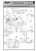
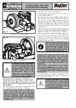
11.0 CONTROLS
11.1 Control device (valid for NAV11N and
NAV11NT models)
The control (handle control) can be moved according
to the positioning necessities of the operator.
MAKE SURE THERE ARE NO PER-
SONS OR OBJECTS HIDDEN TO
THE OPERATOR VISUAL FIELD
BY THE WHEEL SIDE PLAY (ESPE-
CIALLY IN CASE OF WHEELS WITH
LARGE DIMENSIONS).
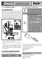
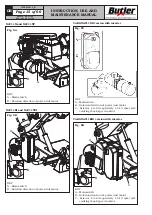
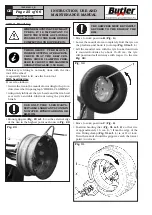
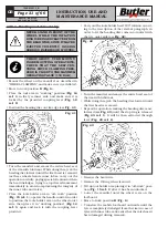
The control (
Fig. 9
) consists of:
•
“A” lower selector
(with protection) three-positions
control for opening and closing of wheel holder man-
drel: a central “firm” position for stop of mandrel
opening/closing movement and two “hold activation”
positions for mandrel jaws opening/closing;
•
“B” lever
three-positions control for tools holder
carriage translation: a central “firm” position for
translation stop and two “hold activation” positions
for carriage supporting translation towards the man-
drel and return;
•
“C” lever
three-positions control for vertical trans-
lation of mandrel arm: central “firm” position for
movement stop and two “hold activation” positions
for arm up and down translation;
•
“D” small lever
control for mandrel clockwise/anti-
clockwise rotation;
A
B
C
B
C
D
Fig.
_
9
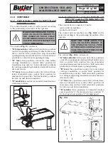
11.2 Control device (only for NAV11N and
NAV11NT models with VARGNAV11ND
version with inverter)
This control device consists of 2 units:
- control unit on machine,
- ground control unit.
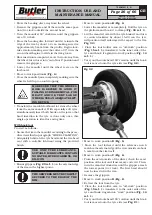
The control unit on machine (see
Fig. 10A
) can be
moved according to the positioning necessities of the
operator.
MAKE SURE THERE ARE NO PER-
SONS OR OBJECTS HIDDEN TO
THE OPERATOR VISUAL FIELD
BY THE WHEEL SIDE PLAY (ESPE-
CIALLY IN CASE OF WHEELS WITH
LARGE DIMENSIONS).
The control (
Fig. 10A
) consists of:
•
“A” lower selector
(with protection) three-positions
control for opening and closing of wheel holder man-
drel: a central “firm” position for stop of mandrel
opening/closing movement and two “hold activation”
positions for mandrel jaws opening/closing;
•
“B” lever
three-positions control for tools holder
carriage translation: a central “firm” position for
translation stop and two “hold activation” positions
for carriage supporting translation towards the man-
drel and return;
•
“C” lever
three-positions control for vertical trans-
lation of mandrel arm: central “firm” position for
movement stop and two “hold activation” positions
for arm up and down translation;
•
“D” selector
, three-positions, for mandrel rotation
speed: position “0” for movement stop, position “1”
for low speed and position “2” for high speed.
Fig. 10A