background image

Revisão

S/E

3/12

A3

01

mm

Formato

Escala

Dimensão

Página

Código matriz

Código sistema

Tol.não especificada

Revisado por: Eduardo Macedo

Aprovado por: Thomas Wang

Modificado por:

Elaborado por: Éber Silva

Data

21/09/10

Documento

Descrição

Liberação inicial

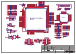
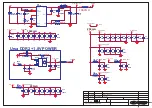
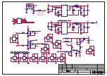
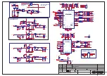
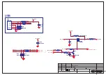
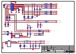
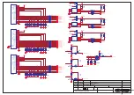
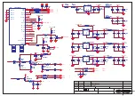
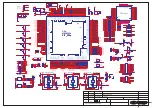
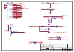
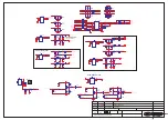
PCI principal HBTV-55D02FD

PW_CTL

ON_USB0_MOS

PB-ADJUST

PB-ON/OFF

ON_PBACK

ADJ-PWM2

POWER-ON/OFF

PB-ADJUST

ON_PANEL

POWER-ON/OFF
PB-ON/OFF

PB-ADJUST

5Vstb

+12V

+5V

+12V

+5V_USB

+5V

+5V

+5V

+5V

+12V

VCC-Panel

+5V

33V_Normal

+12V

5Vstb

+12V

+3.3AVDD

PW_CTL

3

ON_USB0_MOS 9

BRT_CNTL_OUT 3,11

BRT_CNTL_IN

3,11

ON_PBACK

3

ADJ-PWM2

3

ON_PANEL

3

Normal: H

Standby:L

2009-07-16

2009-07-16

2009-07-16

1

2

3

5

4

L8

33uH

L8

33uH

R204
NC

R204
NC

R201
10K

R201
10K

C24
0.1u

C24
0.1u

1
2
3

4

5

6

7

8

9

H5

PAD

H5

PAD

+

CA5
470uF/16V

+

CA5
470uF/16V

C12
0.1u

C12
0.1u

R91

100K

R91

100K

R205
1K

R205
1K

+

C306
NC/100uF/16V

+

C306
NC/100uF/16V

L203

FB

L203

FB

V201
3904

V201
3904

R17

4.7K

R17

4.7K

C20
10n

C20
10n

C305
0.1uF

C305
0.1uF

C7
10n

C7
10n

1
2
3

4

5

6

7

8

9

H14

PAD

H14

PAD

D93
NC/1N5822

D93
NC/1N5822

1

2

3

Q35

3904

Q35

3904

1
2
3

4

5

6

7

8

9

H16

PAD

H16

PAD

R1560

4.7K

R1560

4.7K

1

H12
TPAD

H12
TPAD

1
2
3

4

5

6

7

8

9

H17

PAD

H17

PAD

1

H8
TPAD

H8
TPAD

1
2
3

4

5

6

7

8

9

H10

PAD

H10

PAD

R374

1K

R374

1K

1

1

2

2

3

3

4

4

5

5

6

6

7

7

8

8

9

9

10

10

11

11

12

12

CN10 Power_Main

CN10 Power_Main

C302
2.2uF_NC

C302
2.2uF_NC

R23
6.8K_1%

R23
6.8K_1%

1

H7
TPAD

H7
TPAD

R372

NC/0R

R372

NC/0R

EN

7

FB

5

VCC

2

OUT

3

BST

1

GND

4

SS

8

COMP

6

shield

9

U32

MP1484

U32

MP1484

V204
3904

V204
3904

1

2

3

Q36

3904

Q36

3904

1

H9
TPAD

H9
TPAD

+

CA10
470uF/16V

+

CA10
470uF/16V

R94

NC/100R

R94

NC/100R

R6
31.6K_1%

R6
31.6K_1%

C27
0.1u

C27
0.1u

L109

NC

L109

NC

R208
1K

R208
1K

C25
10n

C25
10n

R206

0

R206

0

C28
10n

C28
10n

+

CA3
100uF/16V

+

CA3
100uF/16V

C301
0.1uF

C301
0.1uF

1
2
3

4

5

6

7

8

9

H4

PAD

H4

PAD

+

CA7
100uF/16V

+

CA7
100uF/16V

R202

0

R202

0

R207
10K

R207
10K

D95

NC/1N5822

D95

NC/1N5822

V202
3904

V202
3904

C21
0.1u

C21
0.1u

L204

NC

L204

NC

R25
6.8K

R25
6.8K

EN

7

FB

5

VCC

2

OUT

3

BST

1

GND

4

SS

8

COMP

6

shield

9

U24

MP1484

U24

MP1484

R1559
470R

R1559
470R

R218
4.7K

R218
4.7K

R28
6.8K_1%

R28
6.8K_1%

C15
0.1u

C15
0.1u

C304
0.1uF

C304
0.1uF

1
2
3

4

5

6

7

8

9

H3

PAD

H3

PAD

R210
100K

R210
100K

1

H13
TPAD

H13
TPAD

1

2

3

N201
AO3401

N201
AO3401

R246
NC/0R

R246
NC/0R

R93

10K

R93

10K

R395
4.7K

R395
4.7K

R10
31.6K_1%

R10
31.6K_1%

1
2
3

4

5

6

7

8

9

H1

PAD

H1

PAD

R373

4.7K

R373

4.7K

R212
22K

R212
22K

R211 NC/0R

R211 NC/0R

R203
4.7K

R203
4.7K

R532

100R

R532

100R

1
2
3

4

5

6

7

8

9

H15

PAD

H15

PAD

1
2
3

4

5

6

7

8

9

H2

PAD

H2

PAD

+

C1467
10uF/16V

+

C1467
10uF/16V

1
2
3

4

5

6

7

8

9

H6

PAD

H6

PAD

1

2

3

V200
3904

V200
3904

1

H11
TPAD

H11
TPAD

1

2

3

5

4

L6

33uH

L6

33uH

C26
0.1u

C26
0.1u

R31
6.8K

R31
6.8K

Summary of Contents for HBTV-55D02FD

Page 1: ... N o existem pe as ou partes que possam ser reparados pelo consumidor final sob riscos de choque el trico causando ferimentos ƒ proibida a distribui o comercializa o ou c pia deste documento HBTV 55D02FD ATEN O 2011 H BUSTER DO BRASIL MANUAL DE SERVIÇO graves Sujeito a modificações ...

Page 2: ...pare Parts 7 1 2 8 Photo used in this manual 7 1 3 How to Read this Service Manual 7 1 3 1 Using icons 8 Chapter 2 Specification 2 1 Specification list 9 2 2 External pictures four faces 10 Chapter 3 Disassemble and Assemble Chapter 4 Location of Controls and Components 4 1 Board Location 14 4 2 Main Board 15 4 2 1 Function Description 15 4 2 2 Connector defi 15 4 3 Power Supply Board 4 3 1 Function...

Page 3: ...View and Parts List 8 2 Initial Procedures Procedimentos Iniciais 36 8 2 1 Nedded tools Ferramentas Necessárias 8 2 2 How to identify the Panel Type Como identificar o modelo de painel 8 2 2 1 Service Menu Mode Menu do Modo de Serviço 8 2 2 2 Rear Side of LCD Panel lado traseiro do painel de LCD 8 2 3 Copying the firmware to USB Memory Key copiando o programa no pen drive 8 3 Updating the Firmware...

Page 4: ...id the possibility to get electrical shock from the live power supply or charged electrical parts even the power is off This symbol indicates that high voltage is present inside It is dangerous to make any kind of contact with any inside part of this product This symbol indicates that there are important operating and maintenance instructions in the literture accompanying the appliance 1 2 2 Be ca...

Page 5: ...ve surface such as aluminum foil to prevent electrostatic charge buildup or exposure of the assembly 1 2 4 About lead free solder PbF This product is manufactured using lead free solder as a part of a movement within the consumer products industry at large to be environmentally responsible Lead free solder must be used in the servicing and repairing of this product 1 2 5 Use the genewing parts spe...

Page 6: ...licator 10 by volume Acetone and 90 by volume isopropyl alcohol 90 99 strength CAUTION This is a flammable mixture Unless specified otherwise in this service manual lubrication of contacts is not required Capacitors may result in an explosion hazard 5 Do not defeat any plug socket B voltage interlocks with which receivers covered by this service manual might be equipped 6 Do not apply AC power to th...

Page 7: ...bserve all other safety precautions 17 Minimize bodily motions when handling unpackaged replacement ES devices Otherwise harmless motion such as the brushing together of your clothes fabric or the lifting of your foot from a carpeted floor can generate static electricity sufficient to damage an ES device 1 2 7 Ordering Spare Parts Please include the following informations when you order parts Partic...

Page 8: ...uable to the reader such as tips and tricks Caution A caution is used when there is danger that the reader through incorrect manipulation may damage equipment loose data get an unexpected result or has to restart part of a procedure Warning A warning is used when there is danger of personal injury Reference A reference guides the reader to other places in this binder or in this manual where he she...

Page 9: ...to 16 9 Resolução 1920 1080 Tempo de Resposta ms 6 ms Ângulo de Visão 178 Contraste 5000 1 Brilho 450 cd m Idioma OSD Ing Por Esp Sistema de Cor PAL NTSC ISDB Tb Sistema de Audio M N Potência de saída W 10W 2 Consumo W 160W Tensão de entrada V 100 240V Frequência Hz 50 60Hz Peso Líquido Kg 28 5 com pedestal Peso Bruto Kg 32 sem pedestal ...

Page 10: ...2 2 External pictures four faces Front Side Left Side 10 Service Manual HBTV 55D02FD ...

Page 11: ...Service Manual 11 Right Side Back Side HBTV 55D02FD ...

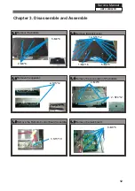
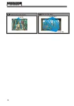
Page 12: ... 1 4 1 3 1 3 1 1 1 X Remove the bottom 5 M4 8 4 M8 8 X Remove the speaker 2 ST3 12 X Remove the back cover 14 ST4 12 X 1 M4 16 X 5 M3 6 X Remove the connection of the bottom 4 M4 8 X 2 ST4 12 X Remove the Remote Control Board Assembly 5 5 1 ST3 10 X Remove the mainboard 6 6 6 M3 6 X ...

Page 13: ...Service Manual 13 HBTV 55D02FD 1 1 Remove the power suuply 7 4 M3 6 X Remove the panel 8 10 ST4 12 X 14 ST3 8 X ...

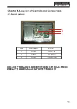
Page 14: ...ents Service Manual 14 Item Parts number Descrição A B Tela de LCD PCI da Fonte 410455 Placa Principal 410453 410455 OBS OS ITENS ACIMA SOMENTE PODEM SER SOLICITADOS MEDIANTE CONSULTA AO SUPORTE TÉCNICO C 4 1 Board Locations HBTV 55D02FD A B C ...

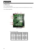
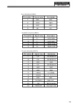
Page 15: ...ipment then translate into signal that panel can display 4 2 2 Connector definition CNB4 CNB3 CN5 CN2 CN4 Remote connectors CNB4 Pin number Signal name Description 5 5VSTB IR IN IR LED_R LED_B GND GND 1 2 3 4 15 Service Manual CN10 CN27 5V Stand LED RED LED BLUE HBTV 55D02FD HBTV 55D02FD ...

Page 16: ...ight of audio Left of audio Right of audio 1 2 3 Pin number Signal name Description Service Manual GND GND KEY0 KEY1 3 3V Power connectors CN10 4 5 6 7 8 9 10 11 12 12V 12V Mainboard 12V 12V GND GND GND GND GND GND 12V Mainboard 12V Mainboard 5VSTB 5V_standby E PWM WHUQDO 3 0 RQWURO GND GND PW ON OFF Pow er on off NC NO Connection PB ON OFF Back light on off HBTV 55D02FD ...

Page 17: ...7 Service Manual HBTV 55D02FD CN3 Pin Nmuber Signal Name 1 24V 2 24V 3 24V 4 24V 5 24V 6 GND 7 GND 8 GND 9 GND 10 GND 12 BL ON OFF 13 STATUS 14 PWM DIMMING 11 NC CN2 Pin Number Signal Name 1 12V 2 12V 3 GND 4 12V 5 GND 6 GND 7 5V 9 GND 10 P ON OFF 12 B ON OFF 8 PWM DI MMI NG 11 NC CN1 Pin Number Singal Name 1 L 2 R ...

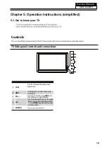
Page 18: ... Press this key to open close signal source options menu 2 MENU Menu display Press to access the on screen menu display 3 VOL Presstoadjustthevolume IntheMENUscreen thesebuttonsserveasright leftbuttons 4 CH Press to scan through channels To scan quickly through channels press and hold down either In the MENU screen these buttons serve as up down buttons 5 POWER HBTV 55D02FD ...

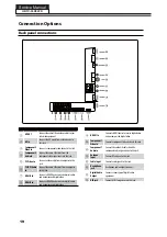
Page 19: ...jack 6 PC DVI Audio In Connect the audio L R cables from a computer to this jack 7 HDMI3 In Connect a HDMI device to receive digital audio and uncompressed digital video 8 HDMI2 In Connect a HDMI device to receive digital audio and uncompressed digital video 9 HDMI1 In Connect a HDMI device to receive digital audio and uncompressed digital video 0 Component1 Video In Connect a component video devi...

Page 20: ...y for USB H 1MBZ 1BVTF CVUUPO Only for USB J USB Press to switch input source to USB in K DNR Digital Noise Reduction L 4 1 CVUUPO Press to display the sleep timer option M CH LIST Open the channel list inTV N FAVORITE Open the favourite channel list inTV O VNCFS CVUUPOT Press to change a channel P INFO Show Informations about the programs and USB files Q Q VIEW Press to jump back and forth betwee...

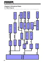
Page 21: ...Ain For Panel For Tuner 5V 12V For 5V Panel 9435 5V 1084 3 3 3 3V Normal power 3 3AVDD AMS1117 adj For DDR2 1 8V AMS1117 3 3 AP1117 1 8 VDD_DE Vcore For Demux 1084 3 3 3 3V Standby power Debug IR 3 3VDD For MCU For ADC Service Manual 21 7KHVH EORFNV PD EH GLIIHUHQW IURP WKH HOHFWULFDO JUDSKLFV UHIHU WR LUFXLW LDJUDP EHORZ HBTV 55D02FD ...

Page 22: ... C8 DQ9 C2 DQ10 D7 DQ11 D3 DQ12 D1 DQ13 D9 DQ14 B1 DQ15 B9 UDQS B7 UDQS A8 UDM B3 LDQS F7 LDQS E8 CS L8 LDM F3 VDD A1 VSS A3 VDDQ A9 VSSQ B8 VSSQ B2 VDDQ C1 VDDQ C7 VDDQ C3 VSSQ D2 VSSQ D8 VDD E1 VSS E3 VSSQ E7 VSSQ F2 VSSQ F8 VDDQ G1 VDDQ G3 VDDQ G7 VDDQ G9 VDDQ E9 VSSQ H2 VSSQ H8 VDDL J1 VREF J2 VSS J3 VSSDL J7 VDD J9 ODT K9 VDD M9 VSS N1 VSS P9 VDD R1 VDDQ C9 VSSQ A7 BA2 RFU2 L1 U65 EDE5116AJBG...

Page 23: ...74 100nF C78 100nF C78 100nF L14 FB0805 L14 FB0805 C72 100nF C72 100nF C60 10uF C60 10uF L16 NC FB1206 L16 NC FB1206 C85 100nF C85 100nF EN 7 FB 5 VCC 2 OUT 3 BST 1 GND 4 SS 8 COMP 6 GND 9 U15 MP1482 U15 MP1482 C71 100nF C71 100nF C67 100nF C67 100nF C318 1n C318 1n C290 2 2uF C290 2 2uF C110 0 1u C110 0 1u C63 100nF C63 100nF R427 10K R427 10K 3 1 2 ADJ IN N206 AMS1117 Adj ADJ IN N206 AMS1117 Adj...

Page 24: ... 5 6 6 7 7 8 8 9 9 10 10 11 11 12 12 CN10 Power_Main CN10 Power_Main C302 2 2uF_NC C302 2 2uF_NC R23 6 8K_1 R23 6 8K_1 1 H7 TPAD H7 TPAD R372 NC 0R R372 NC 0R EN 7 FB 5 VCC 2 OUT 3 BST 1 GND 4 SS 8 COMP 6 shield 9 U32 MP1484 U32 MP1484 V204 3904 V204 3904 1 2 3 Q36 3904 Q36 3904 1 H9 TPAD H9 TPAD CA10 470uF 16V CA10 470uF 16V R94 NC 100R R94 NC 100R R6 31 6K_1 R6 31 6K_1 C27 0 1u C27 0 1u L109 NC ...

Page 25: ...100p C415 100p GND_SUB 1 SA 2 TEST_MODE 3 VSS 4 VCC_REG 5 OUT2B 6 GND2 7 VCC2 8 OUT2A 9 OUT1B 10 VCC1 11 GND1 12 OUT1A 13 GND_REG 14 VDD 15 CONFIG 16 OUT3B DDX3B 17 OUT3A DDX3A 18 EAPD OUT4B 19 TWARN OUT4A 20 VDD_DIG 21 GND_DIG 22 PDN 23 VDD_PLL 24 PLL_FILTER 25 PLL_GND 26 XTI 27 BICKI 28 LRCKI 29 SDI 30 RST 31 INT_LINE 32 SDA 33 SCL 34 GND_DIG 35 VDD_DIG 36 PAD 37 U54 STA559BW U54 STA559BW C367 2...

Page 26: ...B0_DM 3 USB0_DP 3 ON_USB0 3 ON_USB0_MOS 1 USB C215 0 1uF C215 0 1uF 1 2 3 N1206 AO3401 N1206 AO3401 R154 5R R154 5R 1 2 DD27 ESD 0402 DD27 ESD 0402 L120 NC FB220 500mA L120 NC FB220 500mA L71 FB 2A L71 FB 2A CA110 100uF 16V CA110 100uF 16V R160 5R R160 5R C288 1uF 6 3V C288 1uF 6 3V F3 1 5A F3 1 5A 1 2 D76 ESD 0402 D76 ESD 0402 R377 5 1R R377 5 1R 1 VCC 1 2 D 2 3 D 3 4 GND 4 SHIELD 5 SHIELD 6 CN9 ...

Page 27: ...D 0402 D81 ESD 0402 R352 100R R352 100R C277 47n C277 47n 1 6 2 7 3 8 4 9 5 11 12 13 14 15 10 16 17 P8 VGA P8 VGA D79 NC BAT54C D79 NC BAT54C R367 12K R367 12K R346 75R R346 75R R354 4 7K R354 4 7K R344 47R R344 47R 1 2 D57 ESD 0402 D57 ESD 0402 R342 47R R342 47R 1 2 D84 ESD 0402 D84 ESD 0402 C338 0 1u C338 0 1u R359 100R R359 100R R353 100R R353 100R R360 100R R360 100R R358 100R R358 100R 1 2 D8...

Page 28: ...SD 0 15pF 1 2 D46 ESD 0 15pF D46 ESD 0 15pF D45 BAT54C D45 BAT54C R504 4 7K R504 4 7K R320 10R R320 10R R327 4 7K R327 4 7K 1 2 D54 ESD 0402 D54 ESD 0402 DAT2 3 DAT2 1 Dat1 shield 5 DDC SCL 15 DDC SDA 16 DAT1 6 DAT1 4 Dat2 shield 2 5V 18 CEC DDC GND 17 HPD 19 DAT0 9 DAT0 7 Dat0 shield 8 clk shield 11 clk 10 clk 12 CEC 13 SHIELD 20 SHIELD 21 SHIELD 22 SHIELD 23 SHIELD 24 SHIELD 27 SHIELD 28 P6 HDMI...

Page 29: ...3 Q26 MMBT3904 Q26 MMBT3904 R260 4 7K R260 4 7K GND 2 VOUT 3 VIN 1 GND 4 N1 LM7805 N1 LM7805 C1457 0 1u C1457 0 1u C204 33p C204 33p C203 0 1u C203 0 1u R261 100R R261 100R RF_SW 1 GAIN_SW 2 AFT 5 SPBVAL 16 SRDT 17 SRCK 18 BB BOOSTER 3 B1_5V 4 SIF 6 RESET 11 SCL 13 RSEORF 14 SBYTE 15 SDA 12 VIDEO 7 B2_2 5V 8 B3_3 3V 9 B4_1 2V 10 SHIELD 19 SHIELD 20 SHIELD 21 SHIELD 22 SHIELD 23 U51 VA1G5BF8021 U51...

Page 30: ...2 4 6 8 RP12 56RX4 1 3 5 7 2 4 6 8 RP12 56RX4 C196 10n C196 10n C173 0 1u C173 0 1u R172 NC 4 7K R172 NC 4 7K R116 47K R116 47K R413 10K R413 10K R158 4 7K R158 4 7K R166 100R R166 100R 1 3 5 7 2 4 6 8 RP4 22RX4 1 3 5 7 2 4 6 8 RP4 22RX4 R120 56R R120 56R R142 100R R142 100R R110 1K_1 R110 1K_1 R453 56R R453 56R 1 1 3 3 5 5 7 7 9 9 11 11 13 13 15 15 17 17 19 19 21 21 23 23 25 25 27 27 29 29 2 2 4 ...

Page 31: ...C136 0 1u C148 0 1u C148 0 1u L110 FB220 300mA L110 FB220 300mA C107 0 1u C107 0 1u C157 0 1u C157 0 1u C133 2 2u C133 2 2u C126 0 1u C126 0 1u C130 0 1u C130 0 1u C113 0 1u C113 0 1u L103 FB220 300mA L103 FB220 300mA R104 470R_1 R104 470R_1 C149 0 1u C149 0 1u C147 0 1u C147 0 1u C141 0 1u C141 0 1u C163 0 1u C163 0 1u C144 0 1u C144 0 1u R100 10K R100 10K C118 0 1u C118 0 1u C134 0 1u C134 0 1u ...

Page 32: ...5 10 DSMB_CVBS_in 3 IR in 3 DSMB_H SYNC 3 DSMB_V SYNC 3 RCA_AU_IN_3R 3 RCA_AU_IN_3L 3 DSMB_CVBSO 5 VGA_R PR 5 VGA_G Y 5 VGA_B PB 5 C Location near MST IC R545 0 R545 0 DATA2 1 DATA2 SHIELD 2 DATA2 3 DATA1 4 DATA1 SHIELD 5 DAT1A 6 DATA0 7 DATA0 SHIELD 8 DATA0 9 CLK 10 CLK SHIELD 11 CLK 12 CEC 13 NC 14 SCL 15 SDA 16 DDC CEC GND 17 5V POWER 18 HOT PLUG 19 20 20 21 21 23 23 22 22 CN26 DSMB CN26 DSMB R...

Page 33: ...227 47n C227 47n R253 10K R253 10K R542 33K NC R542 33K NC R242 10K R242 10K R239 75R R239 75R R522 220 R522 220 C249 560p C249 560p C237 560p C237 560p R544 220 R544 220 C161 0 1uF NC C161 0 1uF NC C250 47n C250 47n R548 10K R548 10K R541 33K NC R541 33K NC R519 33K NC R519 33K NC 1 2 D25 ESD 0402 D25 ESD 0402 C171 10uF NC C171 10uF NC R230 470R R230 470R C247 2 2u C247 2 2u R241 390R R241 390R C...

Page 34: ... BAS316 L800A 1 QP 34A10 D805 FUR460AMP FB801 3 5 1 C816 68uF 450V C810 68uF 450V R801 51 0603 R811 10 0603 1 2 FB800 3 5 1 1 2 PC601 1 K10103H D302 BAS316 D303 BAS316 R306 1K 0603 R308 20K 0603 C303 22nF 50V 0603 R303 6 81K 0603 C302 100nF 50V 0603 R305 2K 0603 R304 2 15K 0603 T601A B IC301 AS431ANTR E1 CR240A STPS20H100CFP C304 22uF 50V C813 220pF 1KV K MH DP10037 R302 1K 0603 L800B 1 QP 34A10 D...

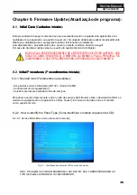
Page 35: ...u de serviços Simplesmente pressione a tecla EXIT no controle remoto do usuário ou desligue o equipamento 7 2 Measurements and Adjustments medições e ajustes NÃO HÁ AJUSTES A SEREM REALIZADOS NESSE MODELO RECOMENDA SE NÃO ALTERAR NENHUM VALOR DE FÁBRICA ATENÇÃO Ao realizar uma atualização de software troca da memória EEPROM ou o aparelho se mostrar instável realize o pro cedimento abaixo Pressione...

Page 36: ...empre o auxílio do suporte técnico da H Buster NUNCA FAÇA ESSE PROCEDIMENTO SE A REDE ELÉTRICA ESTIVER INSTÁVEL SOB RISCO DE DANO IRREVERSÍVEL À MEMÓRIA OU MESMO A PLACA PRINCIPAL RE COMENDAMOS O USO DE NO BREAK PARA A SEGURANÇA DO EQUIPAMENTO 8 2 1 Needed tools Ferramentas necessárias Um pen drive vazio e formatado FAT32 mínimo 512MB Controle remoto do equipamento Versão mais recente baixada do s...

Page 37: ... O nome do arquivo a ser copiado para o pen drive NÃO DEVE SER ALTERADO CASO CONTRÁRIO A TV NÃO IRÁ RECONHECER O ARQUIVO 37 8 3 Updating the firmware Atualizando o programa Siga os procedimentos abaixo atentamente 1 Com o TV funcionando conecte o pen drive com o prgrama gravado na porta USB 2 Aperte a tecla MENU do controle remoto e vá até a opção CANAL com as teclas de navegação e aperte OK 3 Den...

Page 38: ...Service Manual Confira o funcionamento completo do TV sinal digital entradas HDMI Video Compo nente AV etc 8 4 Firmware Update Diagrams Diagramas da atualização de programa HBTV 55D02FD 38 ...

Page 39: ...Service Manual HBTV 55D02FD 39 Chapter 9 Exploded View and Parts List Vista Explodida e Lista de Peças ...

Page 40: ...ificado por Elaborado por Éber Silva Data 28 09 10 Documento Descrição Liberação inicial Vista explodida HBTV 55D02FD Gabinete Frontal 410467 410453 Tela de LCD 410454 Placa Principal 410464 Gabinete Traseiro 410456 Controle Remoto 410469 PCI Sensor IR 410462 Pedestal 410455 PCI Fonte 410470 PCI Teclado 410472 Alto Falante 410471 PCI LED DESCRIÇÃO Nº CÓDIGO QTD ...

Page 41: ...D02FD 410462 PEDESTAL HBTV 55D02FD 410476 CABO DE FORÇA HBTV 55D02FD 410453 TELA CRISTAL LIQUIDO HBTV 55D02FD 410454 PLACA PRINCIPAL HBTV 55D02FD 410455 PCI FONTE HBTV 55D02FD 410456 CONTROLE REMOTO HBTV 55D02FD 410458 CABO LVDS 40 VIAS HBTV 55D02FD 410457 CABO LVDS 34 VIAS HBTV 55D02FD 410477 CABO 2 VIAS AUDIO HBTV 55D02FD 410478 CABO 3 VIAS AV HBTV 55D02FD 410479 CABO 3 VIAS YPbPr 410482 MANUAL ...

Reviews: