


13
C. Turn adjusting nut counterclockwise and slide
engine rearward. Remove old belt.
D. Install new belt onto pulleys. Do not pry belt
onto pulley.
E. Turn adjusting nut clockwise to tighten belt.
Place enough tension on belt to allow not more than
1/2” and not less than 1/4” deflection.
F. Tighten four engine stand bolts.
G. Reinstall belt shield.
3-4 HUB BEARING REPLACEMENT
A. Remove belt shield. (Figure 3-2)
B. Loosen engine mount and remove belt.
C. Loosen set screws and remove 7/16” bolt.
Remove pulley from spindle. Do not lose key.
D. Remove the six nuts securing hub assembly to
deck.
E. Remove upper nut to free spindle retaining nut.
(Figure 3-3)
F. Lift out bushing.
G. Tap spindle out of hub.
H. Remove grease seals and bearings.
I. Check bearing cups inside hub for damage. If
damaged, tap out cup(s), perform step “J” below,
then insert new cup(s).
J. Clean inside of hub with suitable solvent.
NOTE
Check to see if blade needs sharpening or replacing.
K. Insert lower bearing and seal into hub.
L. Install spindle into hub taking care not to dam-
age grease seal.
M. Insert upper bearing, seal and bushing into hub.
Seal should be installed with metal face against bear-
ing to allow grease to purge outward from bearing.
N. Place nut onto spindle. Tighten nut until it takes
7-12 in.lbs. (.79 - 1.35Nm) to turn blade. To measure,
place torque wrench on nut and turn blade while
reading gauge. If nut is too tight, loosen nut two full
turns; tap lightly on top of spindle, then retighten.
After nut is tightened, install jam nut as shown.
NOTE
If a torque wrench is not available, tighten nut until
there is no vertical movement in spindle. Make cer-
tain blade will spin freely.
O. Using a grease gun, fill inside of hub with
multi-purpose grease. Pump in through grease fitting
until grease expels out of upper seal.
P. Install hub assembly to deck and pulley to
spindle.
Q. Install belt and adjust per paragraph 3-2.
R. Install belt shield.
3-5 BLADE REPLACEMENT
Remove old blades. Install new blades with uplift
positioned as shown in Figure 3-3. Torque 3/4 x 2-
1/4” bolts to 297 ft./lbs. and 1/2 x 2” bolts to 76
ft./lbs. Wear heavy gloves to protect hands.
3-6 TROUBLESHOOTING
Troubleshooting procedures are listed in Table 3-1
below. If the problem cannot be solved or replace-
ment parts are necessary, contact your authorized
Bush Hog dealer. Please have ready your machine
name, model number, serial number, purchase date
and exact cause or description of problem.
WARNING
BEFORE PERFORMING MAINTENANCE
INSPECTIONS OR WORK ON CUTTER, SHUT
CUTTER ENGINE OFF AND DISCONNECT
SPARK PLUG WIRE. FAILURE TO DO SO
COULD RESULT IN ACCIDENTAL STARTING
OF ENGINE CAUSING POSSIBLE INJURY OR
DEATH.
NOTE
Engine warranty, service and parts must be
obtained through an authorized service center
for Honda engines.
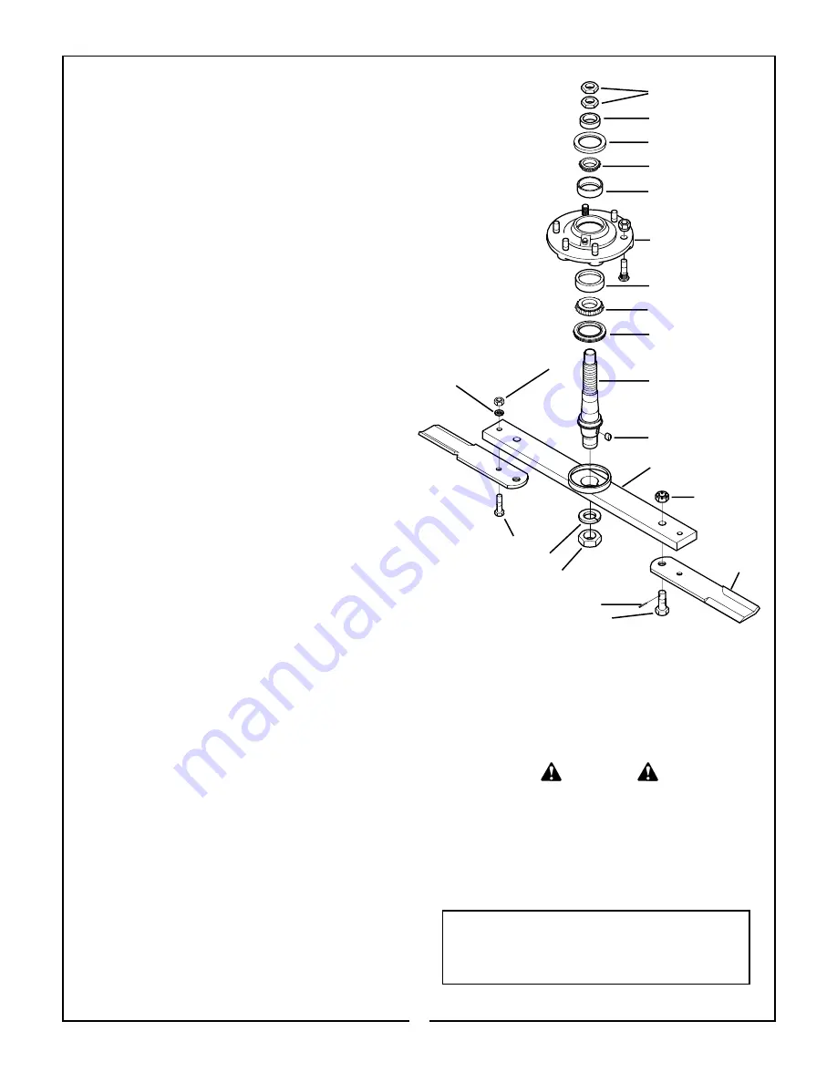
Figure 3-3
Hub And Blade
Assembly
Hex Nuts
Bushing
Oil Seal
Bearing Cone
Outer Bearing Cup
Hub Assembly
Inner Bearing Cup
Bearing Cone
Seal, Triple Lip
Shaft, Spindle
Key
Blade Bar
1/2 x 2” Capscrew
Lockwasher
Hex Jam Nut
Slotted Nut
Cotter Pin
3/4 x 2-1/4” Blade Bolt
Uplift
Blade
Hex Nut
Lockwasher


