background image

3-7 CUTTER BAR HELPER SPRING

ADJUSTMENT 

(9’ MODELS ONLY)

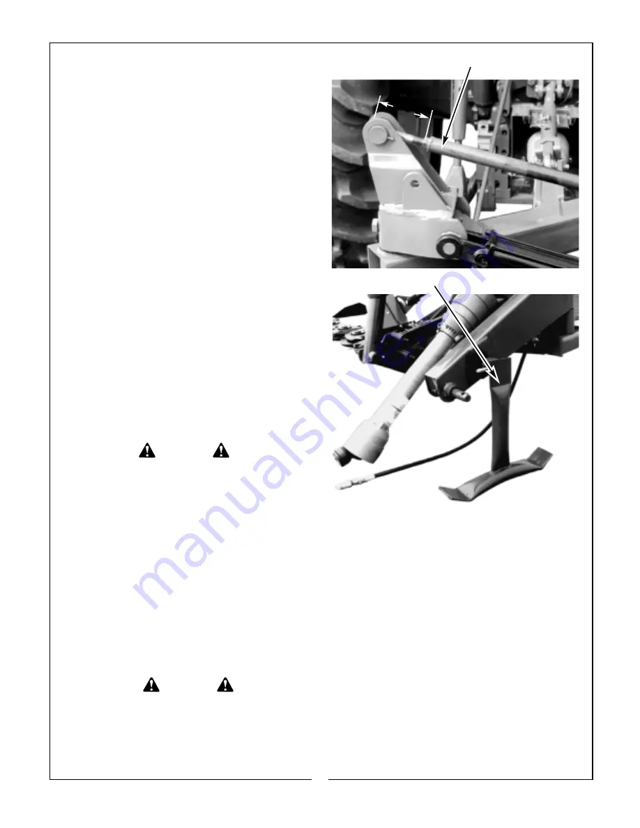
The 9’ models are equipped with a helper spring
assembly to transfer cutter bar weight from the
outer end of the cutter bar back to the frame
assembly.  
The recommended minimum adjustment
measurement is 5-1/2” from under the bolt head to
the end of the rod weldment nut. (Figure 3-5) To
transfer more weight, shorten the measurement. To
transfer less weight, lengthen the measurement. Be
advised, the shorter the measurement, the less the
outer end of the cutter bar can reach down.

3-8 UNHITCHING FROM TRACTOR AND

STORAGE

To prevent rust, always clean all debris from mower
after use. Store in a clean, dry place preferably with
a hard, level floor. Clean and paint any areas where
paint is missing. Apply a light coat of grease to cylin-
der rod..

Unhitch mower as follows:

A. Pin parking stand in the down position as

shown in Figure 3-6.

B. Unfold cutter bar and lower to ground.
C. Lower 3-point hitch to rest on parking stand.

Make certain all pressure is relieved from cutter bar
cylinder.

D. Disconnect PTO driveline, hydraulic hose, and

3-point links.

WARNING

TO AVOID SERIOUS INJURY OR DEATH:
ALWAYS STORE MOWER WITH THE
CUTTER BAR IN THE UNFOLDED
(HORIZONTAL) POSITION.

Figure 3-5              Helper Spring Assembly

5-1/2”

Figure 3-6    Parking Stand

SECTION IV

MAINTENANCE

4-1 MAINTENANCE CHECK LIST

Perform scheduled maintenance as outlined below.
Lower implement to ground, turn off tractor, and set
parking brake before doing maintenance inspections
or work. Some checks may require raising machine
off ground and supporting with blocks. All bolts
should be torqued as indicated in torque at end of
manual unless otherwise indicated.

WARNING

THE MOWER CAN FALL FROM
HYDRAULIC SYSTEM FAILURE. TO AVOID
SERIOUS INJURY OR DEATH, SECURELY
SUPPORT MOWER BEFORE WORKING
UNDERNEATH.

BEFORE EACH USE

1. Perform LUBRICATION per paragraph 4-2.
2. Check blades and spindles to be sure that no

foreign objects such as wire or steel strapping
bands are wrapped around them.

3. Inspect blades for wear. Replace if necessary 

per paragraph 4-3. Always replace both blades 
with two blades equal in weight. 
Use only
genuine Bush Hog replacement parts.

4. Check blade bolts for tightness. Tighten to 50 ft./lbs.
5. Make certain all shields are in place and in good

condition. Repair or replace any missing or dam-
aged shields.

6. Check tractor tire air pressure. Refer to tractor oper-

ator’s manual.

7. During operation, listen for abnormal sounds which 

might indicate loose parts, damaged bearings, or 
other damage. Correct any deficiency before contin-
uing operation.

12

Summary of Contents for GHM 1800 SERIES

Page 1: ...BUSH HOG 1297 Part No 99707 GEARDRIVE HAY MOWERS ASSEMBLY OPERATION MAINTENANCE 4 00 Operator s Manual SERIES GHM 700 GHM 800 GHM 900 GHM 1800 GHM 1900...

Page 2: ...ler we stock genuine Bush Hog parts which are manufactured with the same precision and skill as our original equipment Our trained service personnel are well informed on methods required to service Bu...

Page 3: ...l Customer s responsibility to deliver the product to the authorized Bush Hog Dealer from whom he purchased it for service or replacement of defective parts which are covered by warranty Repairs to be...

Page 4: ...Bush Hog duty taxes charges for normal service or adjustment loss of crops or any other loss of income rental of substitute equipment expenses due to loss damage detention or delay in the delivery of...

Page 5: ...asteners torqued to specifications given in Torque Chart 6 All decals in place and readable See decal page 7 Overall condition good i e paint welds 8 Operators manual has been delivered to owner and h...

Page 6: ...henever anyone comes within the operating area 7 Clear the work area of objects which might be picked up and thrown 8 Use a piece of cardboard or wood rather than hands to search for hydraulic leaks E...

Page 7: ...not limited to instructions to Keep all guards in place when the machine is in operation Permit no riders on equipment Stop engine disconnect the power source and wait for all machine movement to stop...

Page 8: ...h Hog dealer NOTE All references made to right left front rear top or bottom is as viewed facing the direction of forward travel with implement properly attached to tractor 1 2 DESCRIPTION The GHM Fig...

Page 9: ...igure 2 1 that is closest to your situation Hitch pins are reversible to accommodate Cat I or Cat II hitches On larger tractors it may also be necessary to move the right wheel inward The STANDARD con...

Page 10: ...ound as shown in Figure 2 5 G Set tractor 3 point hitch depth control or install the optional check chain assembly to stop with the horizontal main frame pivot approximately 20 inches from the ground...

Page 11: ...port lock in the trans port position Figure 2 6 Place parking stand in the work position as shown in Figure 2 4 Make certain slow moving vehicle SMV sign mounted on rear shield is clean and in good co...

Page 12: ...L FROM TRACTOR AND POSSIBLE INJURY FROM MOWER IT IS RECOM MENDED THAT TRACTOR BE EQUIPPED WITH ROLLOVER PROTECTIVE SYSTEM ROPS AND THAT A SEAT BELT BE USED FOR ALL MOWING OPERATIONS DANGER DANGER E Wi...

Page 13: ...UNFOLDED HORIZONTAL POSITION Figure 3 5 Helper Spring Assembly 5 1 2 Figure 3 6 Parking Stand SECTION IV MAINTENANCE 4 1 MAINTENANCE CHECK LIST Perform scheduled maintenance as outlined below Lower im...

Page 14: ...e trans port position and fasten transport lock Clean any grime and filth from around the fill level plug Add EP80W 90 gear oil if necessary to bring oil level up to the fill hole 6 Overrunning Clutch...

Page 15: ...an equal amount of tension on each belt replace all belts at same time Use only genuine Bush Hog replacement parts Replace as follows A Remove belt shield cover B Loosen jackshaft assembly pivot bolt...

Page 16: ...dirt F Draw a bead of oil resistant gasket sealant Dow Corning 735 sealant recommended by manufacturer around the perimeter of the spin dle housing opening in the cutter bar casing G Position the spin...

Page 17: ...essively tighten to remove sheave from tapered hub Figure 4 11 G Remove the two bolts securing the front mounting lug Figure 4 10 Remove front mounting lug Detach gearbox cutter bar assembly from the...

Page 18: ...broken Reverse or replace Low PTO speed heavy crops Operate at 540 or 1000 rpm High PTO speed light crops Operate at 540 or 1000 rpm Material collecating on cutter bar Reduce cuter bar lift Excessive...

Page 19: ...he blades of adjacent oval discs must be 90 apart from one another as shown above to ensure proper timing 9 MAIN GEARBOX 8 MAIN GEARBOX 7 MAIN GEARBOX FORWARD 1 2 2 2 3 3 3 4 4 4 5 5 5 6 6 7 CW CW CCW...

Page 20: ...this manual 14 Before operating read the maintenance section of this manual to be sure that any parts requiring lubrication such as gearboxes are full to avoid any possible damage BEFORE OPERATING TH...

Page 21: ...am using one 5 8 U bolt lock washer flatwashers and nuts Vent Plug Butt End Cylinder Elbow Figure 5 2 Hydraulic Hose Restrictor Figure 5 1 Assembly Cutter Bar Helper Spring Beam Spring Cushion Hitch A...

Page 22: ...tured Because damage can occur to safety decals either through shipment use or reconditioning Bush Hog will upon request provide safety decals for any of our products in the field at no charge Contact...

Page 23: ...86118 50012616 50012615 86159 78608 78786 22...

Page 24: ...54 480 795 1077 1288 1745 1 11 16 1 1 8 12 UNF 397 538 890 1206 1444 1957 1 7 8 1 1 4 7 UNC 500 678 1120 1518 1817 2462 1 7 8 1 1 4 12 UNF 553 749 1241 1682 2013 2728 2 1 16 1 3 8 6 UNC 655 887 1470 1...

Page 25: ...BUSH HOG L L C P O Box 1039 Selma AL 36702 1039 Telephone 334 874 2700 www bushhog com...

Reviews: