BUSCH 0987 209 539 Instructions Manual Download Page 32

7 | Parameter Description

32 / 44

0870208958_INVEOR_VFD_-0002_PCI_en

4.065 AI2 physical maximum

Selection of the upper limit of a physical value to be displayed:

100 = default value to be adapt to your process

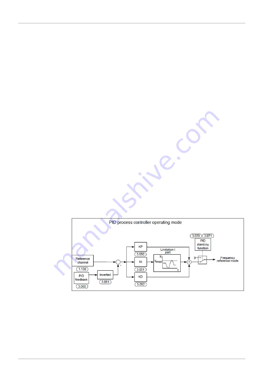
7.7 PID Process Control

7.7.1 Description

In the case of PID process control, the target pressure value and actual pressure value are
compared and the system then regulates to reach the pressure target. This requires to
connect the optional pressure transmitter (part nr. 0653 215 220) to the analogue input
1 or 2.

PID process control:

The target value for the PID process controller is read in percentage steps as in the “fre-
quency setting mode”. 100 % corresponds to the working range of the connected
sensor, which is read in via the actual value input (selected by the “PID actual value”).
Depending on the control difference, a rotation speed value is output to the control out-
put with the help of the amplification factors for the proportional gain (3.050), integral
gain (3.051) and derivative gain (3.052).
In order to prevent the integral share from increasing infinitely in the case of uncontrol-
lable control differences, this value is limited to a specific set value (corresponding to the
“maximum frequency” (1.021)).

PID inverted (usually used in vacuum process):

The PID actual value can be inverted using parameter 3.061. The actual value is impor-
ted inversely, i.e. 0 V … 10 V correspond internally to 100% … 0%.
Please note that the target value must also be defined inversely.

An example:

A sensor with an analogue output signal (0 V… 10 V) is to operate as the source of the
actual value (at AIx). At an output variable of 7 V (70 %), this is to be regulated in-
versely. The internal actual value then corresponds to 100 % – 70 % = 30 %.
In other words, the target value to be specified is 30 %.

Summary of Contents for 0987 209 539

Page 1: ...mp Control Instructions R5 COBRA with Variable Frequency Drive R5 RA RC 0630 B C COBRA NC 0630 C NX 0650 A NX 0950 A 0870208958 0002_en Original instructions Modifications reserved 15 02 2021 Ateliers...

Page 2: ...ters Set Change Values 22 7 3 1 Description 22 7 3 2 How to know if the machine has two set values 22 7 3 3 Parameters not to be changed 22 7 4 Start Stop Functionality 23 7 4 1 Description 23 7 4 2 P...

Page 3: ...has been designed and manufactured according to state of the art meth ods Nevertheless residual risks may remain This instruction manual highlights potential haz ards where appropriate Safety notes a...

Page 4: ...nstructions This document is delivered along with variable frequency drive control device It only contains information about the variable frequency drive parametrisation and con trol Please refer to t...

Page 5: ...729 2 Cable for PC 1 0987 208 730 3 USB Stick including PC Software para meter list factory settings pump con trol instructions 1 0889 209 540 3 2 Application The parameter kit is intended for Parame...

Page 6: ...e Risk of damage to the variable frequency drive The remote control must only be operated with INVEOR variable frequency drive M12 interface socket Connect the cable of the remote control to the M12 i...

Page 7: ...s With these buttons the motor is started or stopped Commands Procedures Next Calling up parameters and submenu Back One menu level higher Cancel End entry without saving Change Call up edit mode curs...

Page 8: ...ode 9 Contains advanced parameters for special uses the expert mode is activated in the main menu The remote control always starts in standard mode x x The INVEOR MMI always starts in standard mode If...

Page 9: ...View of main menu Fig 8 View of parameter group expert mode Part 1 01 Actual values Basic parameter Control mode Process controller Low speed High speed Deceleration 1 Acceleration 1 Deceleration 2 Ac...

Page 10: ...ut AI2 max input AI2 dead time AI2 filter time AI2 function AI2 phy unit AO1 function AO1 min output AI1 max input DO1 function DO1 on DO1 off DO2 function DO1 on DO1 off Relay1 function Relay1 on Rel...

Page 11: ...e Process data out 3 Process data out 10 Process data in 3 Processdata in 6 Motor type i2t fac mot I2T time Opt stat resist Motor current Motor power Motor speed Motor frequency Motor resistance Leaka...

Page 12: ...ts stops of the machine Use the digital start signal The machine will run at the following fixed speed factory settings Machine type Motor frequency R5 RA RC 0630 B 60 Hz R5 RA RC 0630 C 60 Hz COBRA N...

Page 13: ...o commencing any work DANGER Carry out any work on the variable frequency drive and motor Risk of electrical shock Electrical installation work must only be executed by qualified personnel NOTICE Chan...

Page 14: ...e the Machine Make sure that the variable frequency drive is de energised Remove the bridge between 24V Out int power supply and En HW enable hardware in order to avoid any start up Energise the varia...

Page 15: ...nt parameters via PC Software Make sure that the machine is disabled see Disable the Machine 14 Connect the variable frequency drive to the computer with the provided cable Start the PC Software previ...

Page 16: ...l or specific para meters for future purposes NOTE Custom parametrisation via the remote control Please keep a note of each changed parameters As soon as the parametrisation is finished De energise th...

Page 17: ...bled see Disable the Machine 14 Connect the variable frequency drive to the computer with the provided cable Start the PC Software previously installed see PC Software Installation 6 Select Open to lo...

Page 18: ...ram downloading Check the motor parameters match to the motor fitted on the machine As soon as the parametrisation file is loaded De energise the variable frequency drive Reconnect the variable freque...

Page 19: ...ange only the allowed parameters described in the chapter Parameter Description 19 NOTICE Changing of any other parameters than described below Risk of damage to the machine Do not change any other pa...

Page 20: ...s 1 2 1 changeover contact NO NC Maximum switching power at ohmic load cos 1 5 A at 230 V or 30 V at inductive load cos 0 4 and L R 7 ms 2 A at 230 V or 30 V Maximum reaction time 7 ms 0 5 ms Electric...

Page 21: ...ircuit elements such as protector switches and brake coils or circuit elements that are operated via the outputs of the drive controller have to be interference sup pressed RC circuits are suitable as...

Page 22: ...ration 7 3 2 How to know if the machine has two set values If Value 1 and Value 2 are shown in the parameters when opening the parameters list in the software your machine therefore has two set values...

Page 23: ...response to enabling software parameter 1 131 0 immediate start with high signal at input of control enable 1 start only with rising edge at input of control enable 2 digital input 1 function active...

Page 24: ...speed This parameter cannot be changed risk of damage on the machine 7 5 3 Speed Control 3 Fixed Frequency Min Frequency In this configuration if the Digital Input 1 and Digital Input 2 are permanent...

Page 25: ...the operation mode following software enabling 1 131 and hardware en abling the drive controller runs as follows 2 fixed frequencies with the frequencies defined in parameters 2 051 and Minimum freque...

Page 26: ...acteristics Analogue inputs 1 2 In 10 V or 0 20 mA In 2 10 V or 4 20 mA 10 bit resolution Tolerance 2 Voltage input Rin 10 kOhm Current input Working resistance 500 Ohm 7 6 2 Speed Control via Interna...

Page 27: ...m value of the analogue inputs as a percentage of the range Example 0 10 V 0 100 2 10 V 20 100 100 10 V 100 default value to be adapt to your process 4 023 AI1 dead time Dead time as percentage of the...

Page 28: ...rce from which the target value is to be read 1 analogue input 1 4 020 AI1 input type Function of analogue input 1 2 current input 4 021 AI1 standard Low Specifies the minimum value of the analogue in...

Page 29: ...d Control via Analogue Input 2 7 6 4 1 Voltage Input 1 100 Operating mode Selecting the operation mode following software enabling 1 131 and hardware en abling the drive controller runs as follows 0 f...

Page 30: ...3 0 4 063 1 bar 4 063 2 mbar 4 063 3 psi 4 063 4 Pa 4 063 5 m3 h 4 063 6 l min 4 063 7 C 4 063 8 F 4 063 9 m 4 063 10 mm 4 064 AI2 physical minimum Selection of the lower limit of a physical value to...

Page 31: ...to be adapt to your process 4 053 AI2 dead time Dead time as percentage of the range of the analogue input 0 no dead time default value to be adapted to your process 4 054 AI2 filter time second Filt...

Page 32: ...l value Depending on the control difference a rotation speed value is output to the control out put with the help of the amplification factors for the proportional gain 3 050 integral gain 3 051 and d...

Page 33: ...hare of PID controller amplification factor 0 5 should be adapt to your application depending on the pump capacity and cus tomer installation 3 0502 PID D amplification factor Differential share of PI...

Page 34: ...ersely The internal actual value then corresponds to 100 70 30 In other words the target value to be specified is 30 3 069 PID fixed target mode Selection of the digital inputs used for fixed frequenc...

Page 35: ...ing a waiting time the PID stand by time 3 070 with the minimum frequency 1 020 Once the actual value deviates from the target value by the set value the PID stand by hysteresis 3 071 the control the...

Page 36: ...on the variable frequency drive and motor Risk of electrical shock Electrical installation work must only be executed by qualified personnel NOTICE Variable frequency drive maintenance Risk of damage...

Page 37: ...ows the errors to be diagnosed The following table contains an overview Red LED Green LED State Boot loader active flashing in turn Ready for operation activate En_HW for operation Operation ready War...

Page 38: ...EMC interference 10 Parameter distributor The internal distribution of parameters during initialisation failed Parameter set is incomplete 11 Time out power The power part does not respond Operation...

Page 39: ...s motor temperature Motor PTC has been triggered Overload of the motor e g high torque at low motor speed ambient temperature too high 36 Power failure The grid voltage has dropped briefly Grid fluctu...

Page 40: ...ble causes remedy 49 Power class restriction Max overload of the variable fre quency drive exceeded for more than 60 sec Check application reduce load use larger variable frequency drive 53 Motor tipp...

Page 41: ...Note...

Page 42: ...Note...

Page 43: ...Note...

Page 44: ...Japan info busch co jp Korea busch busch co kr Malaysia busch busch com my Mexico info busch com mx Netherlands info busch nl New Zealand sales busch co nz Norway post busch no Peru info busch com pe...

Reviews: