7
EN
TECHNICAL PASSPORT INSTALLATION and OPERATION MANUAL
8
Rivet М8 х 16 mm
6
9
Thermometer
1
10
Probe
1
11
Sensor sleeve
1
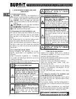
6.3. Check door tightness
Open boiler doors. Place paper strips on the four
sides of the doors and close leaving part of the strips
protruding outside. Pull the paper strips. If the strips
tear upon pulling, doors seal tightly.
*
Caution! Inadequate adjustment of the
hinges may result in air being sucked in
through the doors and the boiler burning
uncontrollably.
7. SETUP OF THE HEATING BOILER
7.1. Connecting the boiler to a chimney
Boiler-to-chimney connection must always comply
with the existing standards and rules. The chimney
must provide sufficient draught for evacuation of the
smoke under any conditions.
The proper functioning of the chimney requires
adequate sizing of the chimney itself since the
draught it produces affects combustion, boiler’s
output and life span.
The draught created by the chimney is in functional
relation to its cross-section, height and the
roughness of its interior walls. No other appliance
may be connected to the chimney serving the boiler.
Chimney diameter must not be smaller than the flue
outlet of the boiler. Flue outlet must be connected
to the chimney opening. In terms of mechanical
properties, the flue outlet must be sturdy and
properly sealed (to avoid gas leak) and allow for easy
access for cleaning on the inside. The inner section of
the flue outlet must not be greater than the effective
section of the chimney and must not narrow. Avoid
using elbow joints.
The chimney cleaning opening has to be in its lowest
part. The chimney‘s wall has to be threeplied where
the medium layer is from mineral wool. The thickness
of the insulation is not less than 30 mm when the
chimney is setting up inside the house and the
thickness is 50 mm, when the setting up is outside.
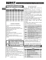
The inner diameter of the chimney depends on its
real height and the power capacity of the boiler (see
diagram 5). Please entrust choosing a chimney and its
installation by a qualified professional. The required
distance between the boiler and the chimney is 300-
600 mm.
Diagram 5. Boiler size and chimney
parameters /see page 56/
Data in the tables are for indicative
purposes.
Draught depends on the diameter, height,
uneven sections along the chimney
surface and differences in temperature of
combustion products and outside air. We
recommend that you use chimney fitted
with flue terminal. Heating specialist must
calculate the precise sizing of the chimney.
7.2. Connecting the thermostatic draft regulator -
air flow regulator
Remove the lever and bolt and tight the thermostatic
regulator to the boiler as shown in the diagram.
Connect the chain to regulator lever and to bottom
door flap. Adjust the flap (diagram 6). (see 9.2.).
Diagram 6 /see page 57/
7.3. Connecting the safety heat exchanger
*
Such connection must be performed by a
technician / service shop authorized for
such operations.
The heating boiler is equipped with safety heat
exchanger (cooling circuit). It connects to the water
system through a thermostatic valve. In case of
overheating, the thermostatic valve feeds in cold
water from the water mains which passes through
the heat exchanger and absorbs the heat in the
boiler. The water is then discharged into the sewage
system. This arrangement ensures safe evacuation
of the excess heat without the need for additional
energy. This guarantees that the water in the boiler
will not exceed the maximum safe level of
95°C
.
The minimum operating pressure of the cooling
water in the safety heat exchanger must be within
the range 2÷10 bar.
A flow rate of at least 12 l/min is required. Connect
the safety heat exchanger according to the hydraulic
diagram using thermostatic valve. Install a filter on
the inlet before the thermostatic valve.
Diagram 7. Connecting the safety heat
exchanger /see page 57/
1. Water supply network (pressure 6-10 bar)
2. Drainage (sewerage)
3. Boiler WBS
4. Safety heat exchanger inlet
5. BVTS valve sensor
6. Safety heat exchanger outlet
7.4. Connecting the boiler to the heating installation.
*
Such connection must be performed by a
technician / service shop authorized for
such operations.
Summary of Contents for WBS 110
Page 2: ......
Page 55: ...55 1 2 3...
Page 57: ...57 6 7...
Page 58: ...58 8...
Page 59: ...59 9...
Page 60: ...60 10...
Page 61: ...61 11...
Page 62: ...62 12 13...
Page 63: ......

