background image

79

Fig. 2: 

ET 200iSP on the Profibus


Select the desired modules from the catalogue listings of the ET200iSP and drag the selection onto the 
respective slot of the ET 200iSP station.

Fig. 3: 

Determine module and slot

Type 8650

english

Commissioning

Summary of Contents for AirLINE Ex 8650

Page 1: ...Operating Instructions Bedienungsanleitung Instructions de Service Type 8650 AirLINE Ex Electrical and Pneumatic Automation System...

Page 2: ...serve the right to make technical changes without notice Technische nderungen vorbehalten Sous res rve de modification techniques 2006 2016 B rkert Werke GmbH Operating Instructions 1601 06_EU EN_0080...

Page 3: ...nts 34 3 Pneumatic Connector Module 41 4 Basic Pneumatic Module 43 5 Terminal module 46 6 Electronic Module 48 7 Valve that can be integrated 51 INSTALLATION 57 1 Safety Instructions 59 2 Installation...

Page 4: ...y 112 2 EC Type Examination Certificate Terminal modules 118 3 IEC Ex Certificate of Conformity Terminal modules 120 4 EC Type Examination Certificate Electronic modules 123 5 IEC Ex Certificate of Co...

Page 5: ...6 1 1 Symbols 6 2 INTENDED USE 7 2 1 Restrictions 7 3 BASIC SAFETY INSTRUCTIONS 8 4 GENERAL INFORMATION 10 4 1 Contact address 10 4 2 Warranty 10 4 3 Approvals 10 4 4 Information on the Internet 10 4...

Page 6: ...ger Failure to observe the warning may result in a fatal or serious injury WARNING Warns of a potentially dangerous situation Failure to observe the warning may result in serious injuries or death CAU...

Page 7: ...ert Correct transportation correct storage and installation and careful use and maintenance are essential for reli able and faultless operation Use the Type 8650 AirLINE Ex 8793 only as intended The A...

Page 8: ...n und nicht mit blo en H nden ber hren General hazardous situations To prevent injury ensure that Do not supply aggressive or inflammable media to the media connections of the system Do not supply flu...

Page 9: ...hich react sensitively to electrostatic discharge ESD Contact with electrostatically charged persons or objects is hazardous to these components In the worst case scenario they will be destroyed immed...

Page 10: ...thorized in accordance with the specified appli cation conditions 4 3 Approvals The approval rating on the B rkert labels refers to B rkert products You can find more detailed information on the appro...

Page 11: ...ION 12 1 1 Product Description 12 1 2 Characteristic Features and Benefits 13 1 3 Field of Application 14 1 4 Marking 14 2 TECHNICAL DATA 15 2 1 General Technical Data 15 2 2 Dimensions 16 3 SYSTEM AC...

Page 12: ...are observed it permits pneumatic electric and elec tronic modules with different functions can be combined with one another The components are connected to each other using screws or latches In this...

Page 13: ...ong service life with oiled and unoiled compressed air thanks to low wear valve function Central exhaust air exhaust Replacement of valves and electronic modules during operation possible thanks to in...

Page 14: ...installed in a control cabinet in the explosion proof area observe the following The control cabinet must be authorized for use in the explosion protected area The control cabinet must be dimensioned...

Page 15: ...nate Approvals A prerequisite for the authorized use of the total AirLINE Ex system is the installation in a suitable certified housing Ex e or Ex d housing for Zone 1 respectively Ex d housing for Zo...

Page 16: ...e Complete System 165 27 7 17 31 5 56 12 5 28 5 10 5 8 25 16 5 3x16 5 49 5 5 5 11 3x11 33 24 12 5 28 5 88 n x 44 n x 66 44 44 35 190 66 44 33 Plug in coupling D6 Screw socket M5 M7 Plug in coupling D8...

Page 17: ...947 Function plates for flange pattern 6526 6527 Installation instead of a 3 2 way or 5 2 way valve 16 5 mm Blind plate complete for 3 2 way and 5 2 way valve 653 765 Supply plate complete for additio...

Page 18: ...ports of the respective valve position As these have smaller cross sections than the ports on the supply segments the possible flow rates are cor respondingly lower For competent advice please contact...

Page 19: ...System Configuration 20 1 2 Siemens SIMATIC ET 200iSP System Components 21 1 3 B rkert AirLINE Ex System Components 21 2 FUNCTION 25 2 1 View of the Overall System 25 2 2 Functional representation of...

Page 20: ...o 48 with 11 mm valves Types 6524 6525 with a middle supply segment up to 32 with 16 5 mm valves Types 6526 6527 with a middle supply segment Mixing 44 mm 66 mm valve segments is possible Maximum widt...

Page 21: ...1 3 1 Module Terminology In order to simplify the overview of the system structure designations have been defined for the modules and assemblies The relationships are explained in the following illus...

Page 22: ...ermediate supply Valve segment 66 mm 4 valve functions Valve segment 66 mm 8 valve functions not yet available Supply segment right Fig 2 Configuration of a complete AirLINE Ex system example 1 3 3 Va...

Page 23: ...23 1 3 4 Electronics Typ ME04 modular electronics Cover flap Electronic module Terminal module Fig 4 Electronics Typ ME04 modular electronics Type 8650 english Configuration and Function...

Page 24: ...lve type 652x EEx i Pneumatic module Fig 5 Bild Pneumatics Type MP13 modular pneumatics The detailed descriptions of the individual modules can be found in chapter Configuration and Function of the Mo...

Page 25: ...s are available via the Siemens SIMATIC ET 200iSP system The AirLINE Ex system can be seamlessly integrated into the Siemens system with the modules of the AirLINE Ex system functioning as digital out...

Page 26: ...I O bus termination module Station 1 5 4 3 2 1 6 7 AirLine Ex Type 8650 Fig 7 Functional representation of an AirLINE Ex system example Legend 1 2 3 4 Supply segment left Valve segment 44 mm 4 valve f...

Page 27: ...nnections 38 2 4 Displays 38 2 5 Channel Assignment 39 2 6 Diagnosis Electronic Module 39 2 7 Accessory 39 2 8 Spare parts 40 3 PNEUMATIC CONNECTOR MODULE 41 3 1 Configuration and Function 41 3 2 Tech...

Page 28: ...Marking 48 6 3 Technical Data 49 6 4 Displays 50 6 5 Diagnosis 50 6 6 Spare Parts 50 7 VALVE THAT CAN BE INTEGRATED 51 7 1 Pneumatic Valves Type 6524 6525 station width 11 mm 52 7 2 Pneumatic Valves...

Page 29: ...not planned in the programs for hardware configuration e g Siemens Step7 As an option versions with an integrated mechanical pressure gauge to display operating pressure are available Fig 1 Supply seg...

Page 30: ...ting Pneumatic ports Unlocking slide only installed on right hand supply segments Pressure gauge optional for displaying operating pressure Shut off slide Power Bus plug Inclined tie rods 2x not insta...

Page 31: ...ensions 190 55 8 137 3 17 31 5 56 10 5 24 27 2 44 164 5 Connections optionally screw socket G3 8 G1 8 NPT3 8 NPT1 8 Fig 3 Dimensions mm Supply segments Type 8650 english Configuration and Function of...

Page 32: ...iliary control air INT Pilot exhaust air 1 8 1 8 3 P 1 Compressed air supply 3 8 3 8 Fig 4 Pneumatic connections Supply segment 1 4 Displays Pressure gauge for displaying operating pressure Fig 5 Oper...

Page 33: ...eft and center 173 368 Terminal module 44 mm passive with locking slide for supply segment right 173 369 Set with various spare parts for valve and module installation seals screws etc 186 877 Pneumat...

Page 34: ...Two different versions 44 66 mm wide for valves of different air capacity are available The different valve func tions can be freely combined Additional pneumatic functions can be integrated as optio...

Page 35: ...nections D45 D6 D1 4 5 D8 5 16 Threaded connections M5 M7 G 1 8 NPT 1 8 Orifice mm 4 6 QNn2 l min 300 700 Opening time3 10 ms 35 80 Closing time3 10 ms 45 90 Pressure range4 bar 2 5 7 2 8 with auxilia...

Page 36: ...hannel status display Hinged cover flap Valves Inclined tie rods 2x Pneumatic service ports Slip in label strip Shut off slide under the valves Power Bus plug Plug for communication bus Valve ejector...

Page 37: ...27 2 44 12 5 28 5 5 5 11 3x11 33 164 5 137 27 Connections optionally Plug in coupling D6 screw socket M5 M7 Fig 8 Dimensions mm Valve segment example station width 44 mm Type 8650 english Configuratio...

Page 38: ...ent them from shifting 1 2 Possible configuration of the service ports Position Valves Double valves 3 2 way 5 2 way 2x 3 2 way 6524 6526 6525 6527 6524 6526 1 not used 2 2 valve 12 2 2 4 4 valve 14 F...

Page 39: ...le Valves Valves 0 3 1 7 0 6 Valves Valves 4 channel module 8 channel module Fig 11 Valve assignment 2 6 Diagnosis Electronic Module Group fault display Yes locally at the electronic module red LED Di...

Page 40: ...s 44 mm station width 171 942 Electronic module 4 channels 16 5 mm for valve segments 66 mm station width 171 943 Electronic module 8 channels 16 5 mm for valve segments 66 mm station width 171 944 Te...

Page 41: ...onnections to the fluidic supply and exhaust of the system and passes this on to the valves Fig 12 Pneumatic supply module part of the supply segment 3 2 Technical Data Pneumatic connections G 3 8 G 1...

Page 42: ...king Function Version G NPT 1 R S 3 5 Exhaust air 3 8 3 8 2 X Control EXT Auxiliary control air INT Pilot exhaust air 1 8 1 8 3 P 1 Compressed air supply 3 8 3 8 Fig 14 Pneumatic Connections Pneumatic...

Page 43: ...Technical Data Pneumatic connections of the valve segment for Valves with station width 11 mm Valves with station width 16 5 mm Plug and socket connection 6 mm 4 mm on request Thread M5 M7 Plug and so...

Page 44: ...dules with Integrated P Shut off General description For the basic pneumatic modules MP 13 in the version for valve types 6524 and 6525 a P shut off integrated into the module is available as an optio...

Page 45: ...ns X channel R S channel P channel Fig 16 Overview Basic pneumatic module Station width 44 mm with the options check valves and P shut off 4 3 Pneumatic Connections 1 2 Possible configuration of the s...

Page 46: ...ane energy and data bus They can not be planned in the hardware configuration programs e g Siemens Step7 Fig 18 Terminal module The EC type examination certificate can be found in the Annex to this op...

Page 47: ...trically active components Type of protection II 2 G Ex e ia ib IIC T4 5 3 1 Overview 2 5 4 6 1 2 3 Legend 1 2 3 4 5 6 Hinge contour for the electronic module Plug connector for the power bus Plug for...

Page 48: ...e g Siemens Step7 During operations the electronic modules can be exchanged individually not more than one at a time Fig 23 Electronic module For 8 channel modules have a look at the chapter Commissio...

Page 49: ...D red for the module status LED green per channel valve function Type of protection II 2 G Ex ib IIC T4 1 These values must be taken into account when calculating the max total power consumption of th...

Page 50: ...es locally at the electronic module red LED Diagnostic functions can be read out using Profibus Channel status diagnosis channel open channel short circuited Individual switching cycle counter for eac...

Page 51: ...n Because from an electrical point of view only the pilot control is important much information is based upon this e g boost time or approval related facts The pilot control system is an independent m...

Page 52: ...without this feature are available Fig 29 Pneumatic valves type 6524 and type 6525 7 1 2 Technical Data Housing material PA polyamide Gasket material NBR Media dry compressed air oiled or oil free neu...

Page 53: ...3 2 1 10 2 x 3 2 way valve pilot controlled current free outlet port 2 and 4 relieved 4 300 0 3 2 5 7 35 45 184 767 184 7682 H 12 3 2 5 14 1 4 5 2 way valve pilot controlled current free outlet port 1...

Page 54: ...hout this feature are available Fig 30 Pneumatic valves type 6526 and type 6527 7 2 2 Technical Data Housing material PA polyamide Gasket material NBR Media dry compressed air oiled or oil free neutra...

Page 55: ...8 80 90 175 6731 175 7231 2 0 3 1 8 80 90 175 7311 D NO normally open 12 3 2 1 10 3 2 way valve pilot controlled current free outlet port 2 pressurized 6 700 0 3 2 8 80 90 175 725 175 7262 H 12 3 2 5...

Page 56: ...56 Type 8650 english Configuration and Function of the Modules...

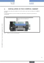
Page 57: ...ET 200iSP Modules 64 4 INSTALLATION IN THE CONTROL CABINET 65 5 CONFIGURATION CONVERSION AND EXPANSION OF AN EXISTING SYSTEM WITH INDIVIDUAL SEGMENTS 66 5 1 System Configuration 66 5 2 Conversion and...

Page 58: ...ION OF THE AIR INLET AND EXHAUST LINES 73 10 1 Connection of the Pressure Supply 73 10 2 Connection of the Exhaust Air 73 10 3 Pilot Exhaust Air Auxiliary Control Air 73 10 4 Plug to Block P channel 7...

Page 59: ...appropriate tools Risk of injury from unintentional activation of the system and an uncontrolled restart Secure system from unintentional activation Following assembly ensure a controlled restart CAUT...

Page 60: ...rged persons or objects is hazardous to these components In the worst case scenario they will be destroyed immediately or will fail after start up Observe the requirements in accordance with EN 61340...

Page 61: ...of the packaging observe the following Take hold of the system by the pneumatic connection modules and take it out of the packaging see figure Holding points Holding points Fig 1 Holding points for r...

Page 62: ...the valves Locking element Unlocking slide Fig 2 Position of the modules to be screwed on Inclined tie rods Fig 3 Position of the tie rods on the installed system Inclined tie rod pocket Fig 4 Two in...

Page 63: ...m out of the profile rail Bring all clamping bolts 1 on the connection modules to the home position by turning them counter clockwise all the way Hook the system in the required position on the upper...

Page 64: ...ed to the AirLINE Ex System Modules which are attached to the right supply segment interlock with the supply segment Removal Using a cross head screwdriver remove the unlocking slide 2 from the supply...

Page 65: ...cabinet can be found in the handbook for the SIMATIC ET200iSP To facilitate replacement of an electronic module the minimum distance indicated in the picture below is recommended Distance to the contr...

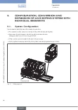
Page 66: ...ules place two modules on the profile rail and push together Now screw the right module to the left one with two inclined tie rods Hexagon socket wrench 3 mm torque 0 6 Nm Other modules can be install...

Page 67: ...segments can be moved until the position is reached in which the system is to be changed When a segment is added first hook it into the upper edge of the profile rail Swivel in the segment and push it...

Page 68: ...of the pressure gauge module Fig 10 Removal installation of a supply segment Valve segments Remove valves and any protective caps from the plug in contacts either depressurized or all affected loca ti...

Page 69: ...gauge module Hook module into the terminal module and swivel in until it engages Valve segment Hook electronic module into the terminal module Actuate locking element in the direction of the arrow and...

Page 70: ...ge contour until it engages Fig 13 Attaching the cover flap 7 2 Removal Swivel open the cover flap and carefully lift the hinge plate over the hinge contour e g using a small cross head screwdriver Fi...

Page 71: ...cken the three screws on the back of the terminal module Re align the pneumatic module on the terminal module Tighten the three screws again Instructions for conversion or expansion of the system Grea...

Page 72: ...a maximum of four valves may be removed at the same time When the valve is being removed a relatively large amount of air is initially released as the P shutoff cannot close until the required pressu...

Page 73: ...aust air to the R S 3 5 connections on the connection modules The exhaust air should be conveyed along the largest possible lines and if required via silencers at high flow rates in order to prevent b...

Page 74: ...connected to port X 10 4 Plug to Block P channel Optionally the pressure supply of the system can be segmented using a partition in the central P channel between two pneumatic modules This allows dif...

Page 75: ...3 Access to the Acyclic Parameters with the Siemens PDM 81 2 4 Example with Two Different Function Modules 86 2 5 Acyclic Parameters of the AirLINE Ex Modules 89 2 6 Use of HSP and SUP under Siemens...

Page 76: ...al activation of the system and an uncontrolled restart Secure system from unintentional activation Following assembly ensure a controlled restart NOTE Operate the system with direct current only To a...

Page 77: ...will not find the information directly Instead you will find a link leading you to the appropriate current versions Siemens Step7 Siemens PCS7 If Siemens Step7 is used an alternative to the method st...

Page 78: ...ystem can be accessed the corresponding GSD file package must be imported into the hardware catalog of the tool Fig 1 Select ET 200iSP Select ET 200iSP in the hardware catalogue and drag it onto the P...

Page 79: ...the Profibus Select the desired modules from the catalogue listings of the ET200iSP and drag the selection onto the respective slot of the ET 200iSP station Fig 3 Determine module and slot Type 8650...

Page 80: ...e same part of the hardware catalogue They are handled in the same way as a digital electric output module Supply segments are passive and are not planned see also chapter Configuration and Function o...

Page 81: ...atalogue of the tool before the AirLINE Ex modules can be accessed When the S7 Manager has started select Extras SIMATIC PDM Manage device catalog via the menu bar Using Search indicate the source dir...

Page 82: ...82 Insert the new object Fig 5 Inserting a new object To insert a new device first select the device type Fig 6 Selection of a new device Type 8650 english Commissioning...

Page 83: ...83 Define the station designation and address Fig 7 Defining the station designation and address Add the function modules Fig 8 Addition of the function modules Type 8650 english Commissioning...

Page 84: ...Define the desired number of identical modules Fig 9 Defining the number of identical modules Select the module type via the menu Allocate Fig 10 Selecting the module type Type 8650 english Commission...

Page 85: ...85 Terminate the module selection with OK Fig 11 Terminating the module selection Type 8650 english Commissioning...

Page 86: ...le with Two Different Function Modules Select the head station Fig 12 Selection of the head station Open the station for access to the acyclic functions Fig 13 Opening the station Type 8650 english Co...

Page 87: ...ccess Fig 14 Selection of the access mode Select the head station to obtain the interface module parameters and to get an overview of the station configuration Fig 15 Parameters of the interface modul...

Page 88: ...88 Fig 16 Parameters of an AirLINE Ex pneumatic module Type 8650 english Commissioning...

Page 89: ...ERKERT ID00171941 Device serial number 00001234 Hardware revision 0 Software revision A 0 0 4 Static revisions no 3 Installation date Initial value Module Slot number 14 Module type 4 DO B rkert 11 mm...

Page 90: ...ith the 8 channel module valves 0 to 3 and or 4 to 7 each make up a group If more than 4 valves are activated at once including the previously activated valve the following might occur Situation 1 No...

Page 91: ...of the channel parameter general Enable channel read write Defines whether or not the channel is enabled for use Behavior at CPU Master STOP read write Defines which value the channel assumes when the...

Page 92: ...5 8 Functions of the diagnosis parameter Group diagnosis read write Indicates whether group diagnostic messages should be generated Broken wire read write Indicates whether a diagnosis message is gen...

Page 93: ...ET 200iSP with the 4 and 8 channel valve modules from AirLINE Ex 2 6 2 Installation of the HSP2033 The hsp2033 zip file is saved and extracted in a directory of your choice Open HW config in STEP 7 S...

Page 94: ...ng HW updates step 2 When the copying process is complete close the dialog field Now select the HSP with the number 2033 and acknowledge with install Fig 19 Installing HW updates step 3 Type 8650 engl...

Page 95: ...95 When the installation is complete the AirLINE Ex 8650 valve modules are included in the hardware catalog Fig 20 HW updates completely installed Type 8650 english Commissioning...

Page 96: ...parameters of a module can be changed via its Object properties Fig 21 Changing the parameters of a module Currently the settings of the switching cycle counters can be changed via SIMATIC PDM only T...

Page 97: ...ce Prior to setup end all SIMATIC applications Start the Buerkert_ET200iSP_SM exe file by double clicking and follow the instructions for setup The installation program checks whether the required STE...

Page 98: ...98 The installation of the Software Update Package is recorded and can be checked under Start SIMATIC Infor mation Installed software Fig 23 SIMATIC Software Type 8650 english Commissioning...

Page 99: ...ial number of all terminal modules The structure of a serialization data record is provided as an example in the chapter Commissioning SD card System Serialization Data Serialization Data Record The d...

Page 100: ...dule ID number of the first valve Serial number of the first valve Data of the valves 2 7 hidden ID number of the last valve Serial number of the last valve ID number of the first terminal module Seri...

Page 101: ...ANCE 103 2 1 Module Maintenance 103 2 2 Cleaning 103 2 3 Diagnosis Function 103 3 MAINTENANCE 104 3 1 Changing Valves During Operation 104 3 2 Changing Electronic Modules During Operation 104 3 3 Trou...

Page 102: ...al activation Following maintenance ensure a controlled restart NOTE Operate the system with direct current only To avoid damaging the system use only direct current as the power supply for the system...

Page 103: ...y Solvents or alcohol are not suitable for cleaning They may attack the plastic parts 2 3 Diagnosis Function 2 3 1 Switching Cycle Counter The current counter readings are stored in the modules at reg...

Page 104: ...lve to the tightening torques indicated in the operating instructions When installing the valve ensure that the service ports are also pressurized in the corresponding rest position of the valve until...

Page 105: ...ectronic module Check whether related valves are faulty or damaged Valves switch with a delay or blow off at the exhaust ports No or insufficient pressure supply Design the pressure supply system with...

Page 106: ...ry out a voltage reset of the module system If an ET200iSP station has started once with Profibus address X the address can be changed as follows Switch off the station Set the address 0 all DIP switc...

Page 107: ...ntents 1 STORAGE 108 1 1 Storage Conditions for Modules in Original Packaging 108 1 2 Shutdown 109 2 PACKAGING TRANSPORT 110 2 1 Transport Conditions for Modules in Original Packaging 110 Type 8650 en...

Page 108: ...applies to modules transported in their original packaging Requirement Admissible range Free fall 1 m Temperature 40 to 70 C Temperature change 20 K h Atmospheric pressure 1080 to 660 hPa correspondi...

Page 109: ...r installation Removal may be carried out by authorized technicians only and with the appropriate tools Risk of injury from unintentional activation of the equipment and an uncontrolled restart Secure...

Page 110: ...ion applies to modules transported in their original packaging Requirement Admissible range Free fall 1 m Temperature 40 to 70 C Temperature change 20 K h Atmospheric pressure 1080 to 660 hPa correspo...

Page 111: ...4 EC TYPE EXAMINATION CERTIFICATE ELECTRONIC MODULES 123 5 IEC EX CERTIFICATE OF CONFORMITY ELECTRONIC MODULES 126 6 EC TYPE EXAMINATION CERTIFICATE 11 MM VALVES TYPE 6104 129 7 IEC EX CERTIFICATE OF...

Page 112: ...l requirements EN 60529 Degrees of protection provided by enclosures IP code EN 61010 1 Safety requirements for electrical equipment for measurement control and laboratory use Part 1 General requireme...

Page 113: ...ive and therefore does not drop below the scope of the Pressure Equipment Directive For the assessment of the products according to the ATEX directive 94 9 EC one or several of the following standards...

Page 114: ...nt for which an EC type examination certificate is available is monitored by Physikalisch Technische Bundesanstalt Bundesallee 100 38116 Braunschweig Such units are labeled with CE0102 The EC type exa...

Page 115: ...03 CAN CSA 22 2 E 60079 11 02 ANSI ISA 60079 0 12 00 01 2005 ANSI ISA 60079 7 12 16 01 2002 ANSI ISA 60079 11 12 02 01 2002 For the FM Ex certification the following standards have been applied FM Cla...

Page 116: ...s based on the certified terminal module Id Nr 00173369 4 For larger systems or systems with larger flow volumes additional terminal segments can be used between the valve segments These are based on...

Page 117: ...3 1 Overview of the valves which can be used depending on the required approval and the electronic modules used Electronic module Max zul ssige Umgebungstemp C1 Approval ATEX IEC Ex FM Ex 171941 4 ch...

Page 118: ...118 2 EC TYPE EXAMINATION CERTIFICATE TERMINAL MODULES Certificate number KEMA 06ATEX0092 Issue Number 2 Type 8650 english Annex...

Page 119: ...119 Type 8650 english Annex...

Page 120: ...120 3 IEC EX CERTIFICATE OF CONFORMITY TERMINAL MODULES Certificate Number KEMA IECExKEM07 0033 Issue Number 0 Type 8650 english Annex...

Page 121: ...121 Type 8650 english Annex...

Page 122: ...122 Type 8650 english Annex...

Page 123: ...123 4 EC TYPE EXAMINATION CERTIFICATE ELECTRONIC MODULES Bescheinigungs Nummer KEMA 06ATEX0093 Ausgabe Nummer 3 Type 8650 english Annex...

Page 124: ...124 Type 8650 english Annex...

Page 125: ...125 Type 8650 english Annex...

Page 126: ...126 5 IEC EX CERTIFICATE OF CONFORMITY ELECTRONIC MODULES Certification Number KEMA IECExKEM07 0032 Issue Number 0 Type 8650 english Annex...

Page 127: ...127 Type 8650 english Annex...

Page 128: ...128 Type 8650 english Annex...

Page 129: ...129 6 EC TYPE EXAMINATION CERTIFICATE 11 MM VALVES TYPE 6104 Certification Number PTB 01ATEX2173 Type 8650 english Annex...

Page 130: ...130 Type 8650 english Annex...

Page 131: ...131 Type 8650 english Annex...

Page 132: ...132 Type 8650 english Annex...

Page 133: ...133 7 IEC EX CERTIFICATE OF CONFORMITY 11 MM VALVES TYPE 6104 Certification Number PTB06 0101 Type 8650 english Annex...

Page 134: ...134 Type 8650 english Annex...

Page 135: ...135 Type 8650 english Annex...

Page 136: ...136 8 EC TYPE EXAMINATION CERTIFCATE 16 5 MM VALVES TYPE 6106 Certification Number PTB 01ATEX2175 Type 8650 english Annex...

Page 137: ...137 Type 8650 english Annex...

Page 138: ...138 Type 8650 english Annex...

Page 139: ...139 Type 8650 english Annex...

Page 140: ...140 9 IEC EX CERTIFICATE OF CONFORMITY 16 5 MM VALVES TYPE 6106 Certification Number PTB06 0102 Type 8650 english Annex...

Page 141: ...141 Type 8650 english Annex...

Page 142: ...142 Type 8650 english Annex...

Page 143: ...143 10 EC TYPE EXAMINTATION CERTIFICATE 11 MM VALVES TYPE 6144 Certification Number PTB 07ATEX2048 Type 8650 english Annex...

Page 144: ...144 Type 8650 english Annex...

Page 145: ...145 Type 8650 english Annex...

Page 146: ...146 Type 8650 english Annex...

Page 147: ...147 Type 8650 english Annex...

Page 148: ...148 Type 8650 english Annex...

Page 149: ...149 11 IEC EX CERTIFICATE OF CONFORMITY 11 MM VALVES TYPE 6144 Certification Number IECEx PTB07 0063 Type 8650 english Annex...

Page 150: ...150 Type 8650 english Annex...

Page 151: ...151 Type 8650 english Annex...

Page 152: ...152 Type 8650 english Annex...

Page 153: ...153 Type 8650 english Annex...

Page 154: ...154 Type 8650 english Annex...

Page 155: ......

Page 156: ...www burkert com...

Reviews: