Operating Instructions
Bedienungsanleitung Manuel d‘utilisation
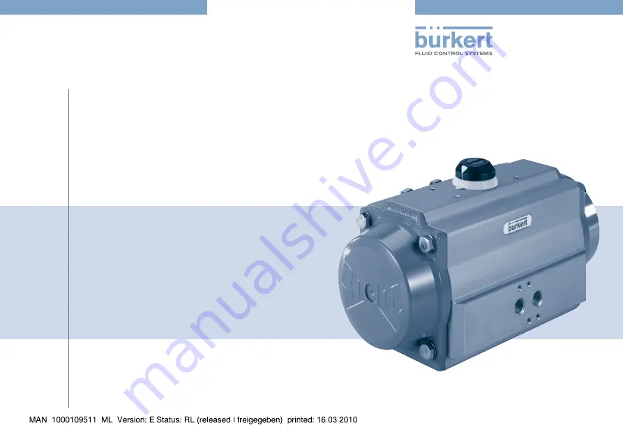
Type 2051
Pneumatic swivel actuatorPneumatischer SchwenkantriebEntraînement pivotant pneumatique
Page 1: ...Operating Instructions Bedienungsanleitung Manuel d utilisation Type 2051 Pneumatic swivel actuator Pneumatischer Schwenkantrieb Entraînement pivotant pneumatique ...
Page 2: ...the right to make technical changes without notice Technische Änderungen vorbehalten Sous réserve de modifications techniques 2008 2010 Bürkert Werke GmbH Operating Instructions 1002 02_EU ML_00805791 Original DE ...
Page 3: ... 6 1 Operating conditions 12 6 2 Conformity with the following standards 12 6 3 General technical data 12 7 Assembly Installation 13 7 1 Safety instructions 13 7 2 Installation 13 7 3 Pneumatic Installation 13 8 Start Up 14 8 1 Safety instructions 14 9 Operation and Function 14 9 1 Safety instructions 14 9 2 Operation of the swivel actuator 14 9 3 Functions 14 10 Maintenance Troubleshooting 15 10 ...
Page 4: ...4 11 Replacement parts 24 12 Shutdown 25 12 1 Safety instructions 25 12 2 Disassembly of the pneumatic swivel actuator 25 13 Packaging Transport 26 14 Storage 26 15 Disposal 26 english Type 2051 ...
Page 5: ...Danger Warns of an immediate danger Failure to observe the warning may result in a fatal or serious injury Warning Warns of a potentially dangerous situation Failure to observe the warning may result in serious injuries or death Caution Warns of a possible danger Failure to observe this warning may result in a moderately severe or minor injury Note Warns of damage to property Failure to observe th...
Page 6: ...ed in chapter 6 Technical Data Correct transportation correct storage and installation and careful use and maintenance are essential for reliable and problem free operation Use the pneumatic swivel actuator type only as intended Restrictions 2 1 If exporting the system device observe any existing restrictions Possible errors in use 2 2 The pneumatic swivel actuator type 2051 may not be operated wi...
Page 7: ...arried out by authorised technicians only and with the appropriate tools After an interruption in the power supply or pneumatic supply ensure that the process is restarted in a defined or controlled manner The device may be operated only when in perfect condition and in consideration of the operating instructions The general rules of technology apply to application planning and operation of the de...
Page 8: ...the printed operating instructions And also on the Internet at www burkert com Bürkert Company Locations Warranty 4 3 This document contains no promise or guarantee Please refer to our general terms of sales and delivery The warranty is only valid if the device type 2051 is used as intended in accordance with the specified application conditions The warranty extends only to defects in the pneumati...
Page 9: ...a rotary piece and an universal interface as per ISO 5211 During the linear movements of the pistons through the pressure force of the control air and the force of the resetting springs the drive shaft is turned via the coupling This rotary movement can be used for the actuation of respective control elements such as ball or butterfly valves Operating principle 5 2 1 Control function A Single acti...
Page 10: ...tuator covers the springs are tensioned Rotation is anti clockwise Exhaust air via connection 4 Connection 2 Connection 4 Clockwise rotation Fig 3 Control function B Counterclockwise rotation Pressure loss or compressed air failure on connection 2 allows the springs to move the pistons inwards Rotation is clockwise Exhaust air via connection 2 Control function I Double acting actuator activation e...
Page 11: ... Fig 4 Control air on connection 2 moves the pistons in the direction of the actuator covers Rotation is anti clockwise Exhaust air via connection 4 Connection 2 Connection 4 Clockwise rotation Fig 5 Control air on connection 4 moves the pistons inwards Rotation is clockwise Exhaust air via connection 2 english Type 2051 ...
Page 12: ...o 17 0 kg depending on actuator design Housing material coated extruded aluminum alloy Sealing material NBR Special FKM on request Pneumatic data 6 3 2 Control medium Compressed air max Particle size 30 µm dry or oiled Pressure range 3 to 8 bar single acting actuator 2 5 to 8 bar double acting actuator Air rate 0 09 to 4 0 l depending on actuator size Connections G 1 8 for actuator size 15 100 G 1...
Page 13: ...ctivation of the system and an uncontrolled restart Secure system from unintentional activation Following assembly ensure a controlled restart Installation 7 2 During the installation please observe the operating instruc tions of the respective fitting Pneumatic Installation 7 3 The swivel actuator can be installed in any position Before installation Make sure that the mechanical connection of the...
Page 14: ...ely trained personnel may operate the equipment the device Operation and Function 9 Safety instructions 9 1 Warning Danger due to improper operation Improper operation may result in injuries as well as damage to the device and the area around it The operating personnel must know and have understood the contents of the operating instructions Observe the safety instructions and intended use Only ade...
Page 15: ...l activation Following maintenance ensure a controlled restart Maintenance work 10 2 It is recommended to perform maintenance after every 500 000 to 1 000 000 circuit connections to guarantee a long service life of swivel actuators If necessary the respective sealing elements must be replaced see the following chapter 10 3 Replacing of the sealing elements For long term operation or rough ambient ...
Page 16: ...roubleshooting 10 3 Replacing of the sealing elements 43 20 07 17 17 1 17 2 17 3 40 15 16 17 14 13 30 09 12 06 60 21 19 5 19 6 50 65 08 01 05 02 04 03 11 39 19 1 19 0 18 10 08 Component overview Fig 6 english Type 2051 ...
Page 17: ... seal 15 2 Piston guide band 16 2 Piston seal 17 min 5 max 12 Pressure spring cartridge 17 1 max 2 Spring for AT045U AT051U Position Number Description 17 2 max 2 Spring for AT045U AT051U 17 3 max 2 Spring for AT045U AT051U 18 1 Retaining ring shaft 19 1 Position indicator for AT051U AT101U 19 0 1 Graduated ring 19 1 1 Position indicator 19 5 1 Adaptor top 19 6 2 Hexagon socket head screw 20 1 Sha...
Page 18: ...me position and that the pistons are all the way in Removing position indicator and graduated ring Pos 19 19 0 19 1 39 19 Removing position indicator Fig 7 Remove screw Pos 39 if fitted Remove position indicator Pos 19 or 19 1 from shaft end If required use a screwdriver as a lever Remove graduated ring Pos 19 0 from housing If required use a screwdriver as a lever Removing the adjusting screws Po...
Page 19: ...al immediately Send actuator back to the supplier 2 4 3 1 2 3 4 5 1 6 2 3 4 5 1 6 7 8 Unscrew cover screws in the sequence Fig 9 Installation of the covers Removing covers from the single acting actuator remove one cover after another Unscrew the cover screws Pos 13 until the covers are no longer under spring force Unscrew the screws completely Remove covers and the springs Removing covers from th...
Page 20: ...a screwdriver and remove the circlip using circlip pliers Remove washer and the outer thrust washer Apply light pressure to the upper side of the shaft Pos 60 until the inner thrust washer Pos 08 and the cams can be removed Remove the shaft from the housing If the shaft does not come out freely carefully tap the upper shaft end using a plastic hammer Remove the upper Pos 06 and lower Pos 07 shaft ...
Page 21: ...n the required position referring to the upper and lower end of the shaft and the direction of rotation of the actuator during operation Insert the inner thrust washer Pos 08 Insert the shaft all the way into the housing Fit the outer thrust washer Pos 08 the support washer Pos 10 and the outer circlip Pos 18 using circlip pliers Installing the pistons Pos 40 Fig 13 Installing the pistons Grease a...
Page 22: ...ng is slightly more than 0 and that dimension A is the same on both sides see Fig 15 Fig 15 Checking dimension A Installing the covers Pos 30 Side A Side B Side A Side B Installation of the covers Fig 16 Grease the housing For single acting actuators insert the springs into the cover according to the required configuration Insert cover seal Pos 14 into the groove Place the covers on the housing Po...
Page 23: ...position is reached Secure by tightening the nut Pos 04 90 opening end position setting unscrew the left adjusting screw until the required end position is reached Secure by tightening the nut Pos 04 Installing the graduated collar and the position indicator Pos 19 19 0 19 1 Placing graduated collar on the housing Fig 18 Place the graduated collar Pos 19 0 on the housing Align adapter Pos 19 5 and...
Page 24: ... replacement parts may cause injuries and damage the device and the surrounding area Use only original accessories and original replacement parts from Bürkert Complete replacement parts kits are offered as replacement parts Depending on the actuator size they have the following order numbers Actuator size Description Order no 10 Replacement part HD38 Special NBR 770 810 15 Replacement part HD38 Sp...
Page 25: ...er 10 Maintenance Troubleshooting Shutdown 12 Safety instructions 12 1 Warning Risk of injury from improper disassembly Installation may be carried out by authorised technicians only and with the appropriate tools Disassembly of the pneumatic 12 2 swivel actuator During the disassembly please observe the operating instructions of the respective fitting english Type 2051 ...
Page 26: ...e permitted storage temperature Storage 14 Note Incorrect storage may damage the device Store the device in a dry and dust free location Storage temperature 40 40 C Disposal 15 Dispose of the device and packaging in an environmentally friendly manner Note Damage to the environment caused by device components contaminated with media Observe applicable regulations on disposal and the environment Not...
Page 27: ...ne Beschreibung 33 6 Technische Daten 36 6 1 Betriebsbedingungen 36 6 2 Konformität mit folgenden Normen 36 6 3 Allgemeine Technische Daten 36 7 Montage Installation 37 7 1 Sicherheitshinweise 37 7 2 Montage 37 7 3 Pneumatische Installation 37 8 Inbetriebnahme 38 8 1 Sicherheitshinweise 38 9 Bedienung und Funktion 38 9 1 Sicherheitshinweise 38 9 2 Bedienung des Schwenkantriebs 38 9 3 Funktionen 38...
Page 28: ...28 11 Ersatzteile 48 12 AuSSerbetriebnahme 49 12 1 Sicherheitshinweise 49 12 2 Demontage des pneumatischen Schwenkantriebs 49 13 Verpackung Transport 50 14 Lagerung 50 15 Entsorgung 50 Typ 2051 deutsch ...
Page 29: ...llungsmittel 1 1 Gefahr Warnt vor einer unmittelbaren Gefahr Bei Nichtbeachtung sind Tod oder schwere Verletzungen die Folge Warnung Warnt vor einer möglicherweise gefährlichen Situation Bei Nichtbeachtung drohen schwere Verletzungen oder Tod Vorsicht Warnt vor einer möglichen Gefährdung Nichtbeachtung kann mittelschwere oder leichte Verletzungen zur Folge haben Hinweis Warnt vor Sachschäden Bei N...
Page 30: ...tel 6 Technische Daten beschrieben Voraussetzungen für den sicheren und einwandfreien Betrieb sind sachgemäßer Transport sachgemäße Lagerung und Instal lation sowie sorgfältige Bedienung und Instandhaltung Setzen Sie den pneumatischen Schwenkantrieb Typ 2051 nur bestimmungsgemäß ein Beschränkungen 2 1 Beachten Sie bei der Ausfuhr des Systems Gerätes gegebenenfalls bestehende Beschränkungen Vorhers...
Page 31: ...o risiertem Fachpersonal mit geeignetem Werkzeug ausgeführt werden Nach einer Unterbrechung der elektrischen oder pneumatischen Versorgung ist ein definierter oder kontrollierter Wiederanlauf des Prozesses zu gewährleisten Das Gerät darf nur in einwandfreiem Zustand und unter Beach tung der Bedienungsanleitung betrieben werden Für die Einsatzplanung und den Betrieb des Gerätes müssen die allgemein...
Page 32: ...sanleitung Außerdem im Internet unter www burkert com Bürkert Company Locations Gewährleistung 4 3 Diese Druckschrift enthält keine Garantiezusagen Wir verweisen hierzu auf unsere allgemeinen Verkaufs und Lieferbedingungen Voraus setzung für die Gewährleistung ist der bestimmungsgemäße Gebrauch des Gerätes unter Beachtung der spezifizierten Einsatzbedingungen Die Gewährleistung erstreckt sich nur ...
Page 33: ...ng zu einem Drehstück und einer universellen mecha nischen Schnittstelle nach ISO 5211 Bei der linearen Bewegung des Kolbens durch die Druckkraft der Steuerluft bzw die Kraft der Rück stellfedern wird über die Kopplung die Antriebswelle um 90 gedreht Diese Drehbewegung kann zur Betätigung entsprechender Stellglieder wie Kugelventile Kugelhähne oder Absperrklappen genutzt werden Funktionsprinzip 5 ...
Page 34: ...werden gespannt Eine Drehung gegen den Uhr zeigersinn wird erreicht Abluft über Anschluss 4 Anschluss 2 Anschluss 4 Drehung im Uhrzeigersinn Bild 3 Steuerfunktion B Drehung gegen den Uhrzeigersinn Entlüftung oder Druckluftausfall an Anschluss 2 ermöglicht den Federn die Kolben nach innen zu bewegen Eine Drehung im Uhrzeigersinn wird erreicht Abluft über Anschluss 2 Steuerfunktion I Doppeltwirkende...
Page 35: ...ft auf Anschluss 2 bewegt die Kolben in Richtung Antriebs deckel Eine Drehung gegen den Uhrzeigersinn wird erreicht Abluft über Anschluss 4 Anschluss 2 Anschluss 4 Drehung im Uhrzeigersinn Bild 5 Steuerluft auf Anschluss 4 bewegt die Kolben nach innen Eine Drehung im Uhrzeigersinn wird erreicht Abluft über Anschluss 2 Typ 2051 deutsch ...
Page 36: ...7 0 kg je nach Antriebsausführung Gehäusematerial beschichtete fließgepresste Aluminiumlegierung Dichtungsmaterial NBR Spezial FKM auf Anfrage Pneumatische Daten 6 3 2 Steuermedium Druckluft gefiltert max Partikelgröße 30 µm Druckbereich 3 bis 8 bar einfachwirkender Antrieb 2 5 bis 8 bar doppeltwirkender Antrieb Luftleistung 0 09 bis 4 0 l je nach Antriebsgröße Anschlüsse G 1 8 bei Antriebsgröße 1...
Page 37: ...er Anlage und unkontrollierten Wiederanlauf Anlage vor unbeabsichtigtem Betätigen sichern Nach der Montage einen kontrollierten Wiederanlauf gewährleisten Montage 7 2 Beachten Sie für die Montage die Bedienungsanleitung der jeweiligen Armatur Pneumatische Installation 7 3 Die Schwenkantriebe können in jeder Position eingebaut werden Vor der Installation Versichern Sie sich dass die mechanische Ver...
Page 38: ... beachtet werden Nur ausreichend geschultes Personal darf die Anlage das Gerät in Betrieb nehmen Bedienung und Funktion 9 Sicherheitshinweise 9 1 Warnung Gefahr durch unsachgemäßen Bedienung Nicht sachgemäße Bedienung kann zu Verletzungen sowie Schäden am Gerät und seiner Umgebung führen Das Bedienungspersonal muss den Inhalt der Bedienungsan leitung kennen und verstanden haben Die Sicherheitshinw...
Page 39: ...chtigtem Betätigen sichern Nach der Wartung einen kontrollierten Wiederanlauf gewährleisten Wartungsarbeiten 10 2 Um eine lange Lebensdauer der Schwenkantriebe zu gewährleisten wird eine Wartung alle 500 000 bis 1 000 000 Schaltungen emp fohlen Gegebenenfalls müssen die entsprechenden Dichtelemente gewechselt werden siehe nachfolgendes Kapitel 10 3 Wechseln der Dichtelemente Bei Dauerbetrieb oder ...
Page 40: ... Fehlerbehebung 10 3 Wechseln der Dichtelemente 43 20 07 17 17 1 17 2 17 3 40 15 16 17 14 13 30 09 12 06 60 21 19 5 19 6 50 65 08 01 05 02 04 03 11 39 19 1 19 0 18 10 08 Bauteile Übersicht Bild 6 Typ 2051 deutsch ...
Page 41: ...dichtung 15 2 Kolbenführungsband 16 2 Kolbendichtung 17 min 5 max 12 Druckfederpatrone 17 1 max 2 Druckfeder für AT045U AT051U Position Anzahl Beschreibung 17 2 max 2 Druckfeder für AT045U AT051U 17 3 max 2 Druckfeder für AT045U AT051U 18 1 Sicherungsring Welle 19 1 Stellungsanzeige für AT051U AT101U 19 0 1 Skalenring 19 1 1 Stellungsanzeige 19 5 1 Adapter oben 19 6 2 Innensechskantschraube 20 1 W...
Page 42: ...ng und mit den Kolben vollständig innen steht Demontage der Stellungsanzeige und des Skalenrings Pos 19 19 0 19 1 39 19 Demontage der Stellungsanzeige Bild 7 Schraube Pos 39 entfernen wenn vorhanden Stellungsanzeige Pos 19 oder 19 1 von der Welle abheben Notfalls Schraubendreher als Hebel verwenden Skalenring Pos 19 0 vom Gehäuse abheben Notfalls Schrau bendreher als Hebel verwenden Demontage der ...
Page 43: ...brechen Antrieb zum Lieferanten zurückschicken 2 4 3 1 2 3 4 5 1 6 2 3 4 5 1 6 7 8 Deckelschrauben in der Reihenfolge herausdrehen Bild 9 Deckeldemontage Deckeldemontage des einfachwirkenden Antriebs einen Deckel nach dem anderen demontieren Die Deckelschrauben Pos 13 herausdrehen bis die Deckel nicht mehr unter Federkraft stehen Die Schrauben komplett ausdrehen Deckel und die Federn entnehmen Dec...
Page 44: ...ngsring mit einer Sicherungsringzange entfernen Unterlegscheibe und die äußere Anlaufscheibe entfernen Mit leichtem Druck auf die Oberseite der Welle Pos 60 drücken bis es möglich ist die innere Anlaufscheibe Pos 08 und die Nocken zu entfernen Die Welle aus dem Gehäuse entnehmen Sollte die Welle nicht leichtgängig herausgehen vorsichtig mit einem Kunstoffhammer auf das obere Wellenende schlagen Di...
Page 45: ...Gehäuse Pos 50 einführen die Nocke Pos 01 in der gewünschten Position einbauen bezogen auf das obere und untere Ende der Welle und der Drehrichtung des Antriebs in Funktion Die innere Anlaufscheibe Pos 08 einsetzen Die Welle vollständig in das Gehäuse einbauen Die äußere Anlaufscheibe Pos 08 die Stützscheibe Pos 10 und den äußeren Sicherungsring Pos 18 mit einer Sicherungs ringzange montieren Mont...
Page 46: ...renen Kolben sicherstellen dass die erreichte Drehung im Bezug zur Achse des Gehäuses etwas mehr als 0 beträgt und dass das Maß A auf beiden Seiten gleich ist siehe Bild 15 Bild 15 Maß A kontrollieren Montage der Deckel Pos 30 Seite A Seite B Seite A Seite B Deckelmontage Bild 16 Das Gehäuse einfetten Bei einfachwirkenden Antrieben die Federn je nach gewünschter Konfiguration in den Deckel einsetz...
Page 47: ...Endstellung erreicht wird Zur Sicherung ziehen Sie die Mutter Pos 04 fest 90 Öffnen Endlageneinstellung die linke Einstellschraube ausdrehen bis die gewünschte Endstellung erreicht wird Zur Sicherung ziehen Sie die Mutter Pos 04 fest Montage des Skalenrings und der Stellungsanzeige Pos 19 19 0 19 1 Skalenring auf das Gehäuse aufsetzen Bild 18 Den Skalenring Pos 19 0 auf das Gehäuse aufsetzen Adapt...
Page 48: ...eeignete Ersatzteile können Ver letzungen und Schäden am Gerät und dessen Umgebung verursachen Nur Originalzubehör sowie Originalersatzteile der Firma Bürkert verwenden Als Ersatzteile werden komplette Ersatzteilsätze angeboten Diese haben je nach Antriebsgröße folgende Bestellnummern Antriebs größe Bezeichnung Bestell Nr 10 Ersatzteilset HD38 Spezial NBR 770 810 15 Ersatzteilset HD38 Spezial NBR ...
Page 49: ...nden Sie im Kapitel 10 Wartung Fehlerbehebung AuSSerbetriebnahme 12 Sicherheitshinweise 12 1 Warnung Verletzungsgefahr bei unsachgemäßer Demontage Die Demontage darf nur autorisiertes Fachpersonal mit geeigne tem Werkzeug durchführen Demontage des pneumatischen 12 2 Schwenkantriebs Beachten Sie für die Demontage die Bedienungsanleitung der jeweiligen Armatur Typ 2051 deutsch ...
Page 50: ...ung der zulässigen Lagertempe ratur vermeiden Lagerung 14 Hinweis Falsche Lagerung kann Schäden am Gerät verursachen Gerät trocken und staubfrei lagern Lagertemperatur 40 40 C Entsorgung 15 Entsorgen Sie das Gerät und die Verpackung umweltgerecht Hinweis Umweltschäden durch von Medien kontaminierte Geräteteile Geltende Entsorgungsvorschriften und Umweltbestimmungen einhalten Hinweis Beachten Sie d...
Page 51: ...itions d exploitation 60 6 2 Conformité avec les normes suivantes 60 6 3 Caractéristiques techniques générales 60 6 4 Caractéristiques pneumatiques 60 7 Montage Installation 61 7 1 Consignes de sécurité 61 7 2 Montage 61 7 3 Installation pneumatique 61 8 Mise en service 62 8 1 Consignes de sécurité 62 9 Utilisation et fonctionnement 62 9 1 Consignes de sécurité 62 9 2 Utilisation de l entraînement...
Page 52: ...ièces de rechange 72 12 Mise hors service 73 12 1 Consignes de sécurité 73 12 2 Démontage de l entraînement pivotant pneumatique 73 13 Emballage Transport 74 14 Stockage 74 15 Elimination 74 Type 2051 français ...
Page 53: ... contre un danger imminent Le non respect peut entraîner la mort ou de graves blessures Avertissement Met en garde contre une situation éventuellement dangereuse Risque de blessures graves voire la mort en cas de non respect Attention Met en garde contre un risque possible Le non respect peut entraîner des blessures légères ou de moyenne gravité Remarque Met en garde contre des dommages matériels ...
Page 54: ...éristiques techniques Les conditions pour l utilisation sûre et parfaite sont un trans port un stockage et une installation dans les règles ainsi qu une parfaite utilisation et maintenance Veillez à ce que l utilisation de l entraînement pivotant pneumati que type soit toujours conforme Limitations 2 1 Lors de l exportation du système de l appareil veuillez respecter les limitations éventuelles ex...
Page 55: ...quement par des techniciens qualifiés et habilités disposant de l outillage approprié Après une interruption de l alimentation électrique ou pneuma tique un redémarrage défini ou contrôlé du processus doit être garanti L appareil doit être utilisé uniquement en parfait état et en respec tant les instructions de service Les règles générales de la technique sont d application pour planifier l utilis...
Page 56: ...t sous www burkert com Bürkert Company Locations Garantie légale 4 3 Cet imprimé ne contient aucune promesse de garantie A cet effet nous renvoyons à nos conditions générales de vente et de livraison La condition pour bénéficier de la garantie légale est l utilisation conforme de l appareil dans le respect des conditions d utilisation spécifiées La garantie ne couvre que l absence de défaut de l e...
Page 57: ...otatif et d une interface mécanique universelle selon ISO 5211 Lors du déplacement linéaire des pistons par la force de pression de l air de commande ou la force des ressorts de rappel la rotation de l arbre d entraînement se fait par l intermédiaire de l accou plement Cette rotation peut être utilisée pour actionner des éléments de réglage comme par ex des robinets à bille ou des clapets d arrêt ...
Page 58: ...l en résulte une rotation dans le sens contraire des aiguilles d une montre Echappement via le raccord 4 Raccordement 2 Raccordement 4 Rotation dans le sens des aiguilles d une montre fonction Fig 3 de commande B rotation dans le sens contraire des aiguilles d une montre L échappement ou panne d air comprimé au raccord 2 permet aux ressorts de rentrer les pistons Il en résulte une rotation dans le...
Page 59: ...e les pistons en direction des couvercles d actionneur Il en résulte une rotation dans le sens contraire des aiguilles d une montre Echappement via le raccord 4 Raccordement 2 Raccordement 4 Rotation dans le sens des aiguilles d une montre Fig 5 L air de commande au raccord 4 fait rentrer les pistons Il en résulte une rotation dans le sens des aiguilles d une montre Echappement via le raccord 2 Ty...
Page 60: ...sion de l entraînement Matériau du boîtier Alliage aluminium extrudé à revêtement Matériau d étanchéité NBR Spécial FKM sur demande Caractéristiques pneumatiques 6 4 Fluide de commande Air comprimé filtré max Taille des parti cules 30 µm sec ou huilé Plage de pression 3 à 8 bar entraînement simple effet de 2 5 à 8 bar entraînement double effet Débit d air 0 09 à 4 0 l selon la taille de l entraîne...
Page 61: ... la mise en marche involontaire de l installation et le redémarrage non contrôlé Empêchez tout actionnement involontaire de l installation Garantissez un redémarrage contrôlé après le montage Montage 7 2 Lors du montage veuillez respecter les instructions de service de la robinetterie concernée Installation pneumatique 7 3 La position de montage des entraînements pivotants est indifférente Avant I...
Page 62: ...service uniquement par un personnel suffisamment formé Utilisation et 9 fonctionnement Consignes de sécurité 9 1 Avertissement Danger dû à une utilisation non conforme Une utilisation non conforme peut entraîner des blessures et endommager l appareil et son environnement Les opérateurs doivent connaître le contenu des instructions de service et les avoir comprises Respectez les consignes de sécuri...
Page 63: ... tout actionnement involontaire de l installation Garantissez un redémarrage contrôlé après la maintenance Travaux de maintenance 10 2 Pour garantir une longue durée de vie des entraînements pivotants nous recommandons une maintenance tous les 500 000 à 1 000 000 cycles Si nécessaire les éléments d étanchéité doivent être remplacés voir la section suivante 10 3 Remplacement des éléments d étanchéi...
Page 64: ...annage 10 3 Remplacement des éléments d étanchéité 43 20 07 17 17 1 17 2 17 3 40 15 16 17 14 13 30 09 12 06 60 21 19 5 19 6 50 65 08 01 05 02 04 03 11 39 19 1 19 0 18 10 08 Aperçu des composants Fig 6 Type 2051 français ...
Page 65: ...Bande de guidage de piston 16 2 Joint de piston 17 min 5 max 12 Cartouche à ressort de pression Position Nombre Description 17 1 max 2 Ressort de pression pour AT045U AT051U 17 2 max 2 Ressort de pression pour AT045U AT051U 17 3 max 2 Ressort de pression pour AT045U AT051U 18 1 Bague d arrêt arbre 19 1 Indicateur de position pour AT051U AT101U 19 0 1 Anneau gradué 19 1 1 Indicateur de position 19 ...
Page 66: ...es pistons complète ment rentrés Démontage de l indicateur de position et de l anneau gradué pos 19 19 0 19 1 39 19 Démontage de l indicateur de position Fig 7 Le cas échéant retirer la vis pos 39 Soulever l indicateur de position de l arbre pos 19 ou 19 1 Si nécessaire utiliser un tournevis comme levier Soulever l anneau gradué pos 19 0 du corps Si nécessaire utiliser un tournevis comme levier Dé...
Page 67: ...ment le démontage Retourner l actionneur au fournisseur 2 4 3 1 2 3 4 5 1 6 2 3 4 5 1 6 7 8 Dévisser les vis de couvercle dans l ordre Fig 9 Démontage des couvercles Démontage des couvercles de l actionneur à simple effet démonter un couvercle après l autre Dévisser les vis de couvercle pos 13 jusqu à ce que les cou vercles ne soient plus soumis à la force du ressort Dévisser complètement les vis ...
Page 68: ...c une pince adéquate Retirer la rondelle et le disque auto lubrifiant externe Exercer une légère pression sur le dessus de l arbre pos 60 jusqu à ce qu il soit possible de retirer le disque auto lubrifiant interne pos 08 et les cames Sortir l arbre du corps Si la sortie de l arbre s avérait difficile taper avec précaution sur l extrémité d arbre supérieure avec un marteau en plastique Retirer les ...
Page 69: ...ion souhaitée par rapport aux extré mités d arbre supérieure et inférieure et au sens de rotation de l actionneur en marche Installer le disque auto lubrifiant interne pos 08 Monter l arbre complètement dans le corps Monter le disque auto lubrifiant externe pos 08 le disque de support pos 10 et la bague de sécurité externe pos 18 avec une pince adéquate Montage des pistons pos 40 Fig 13 Montage de...
Page 70: ...er que la rotation obtenue est légèrement supérieure à 0 par rapport à l axe du corps et que la cote A est identique des deux côtés voir Fig 15 Fig 15 Contrôler la cote A Montage des couvercles pos 30 Part A Part B Part A Part B Montage des couvercles Fig 16 Graisser le corps Pour les actionneurs à simple effet mettre les ressorts en place dans le couvercle selon la configuration souhaitée Placer ...
Page 71: ... souhaitée soit atteinte Serrer l écrou pos 04 pour assurer le blocage 90 ouvrir réglage de la position finale dévisser la vis de réglage gauche jusqu à ce que la position finale souhaitée soit atteinte Serrer l écrou pos 04 pour assurer le blocage Montage de l anneau gradué et de l indicateur de position pos 19 19 0 19 1 Placer l anneau gradué sur le corps Fig 18 Placer l anneau gradué pos 19 0 s...
Page 72: ...nge inadaptées peuvent provoquer des blessures et endommager l appareil ou son environnement Utilisez uniquement des accessoires ainsi que des pièces de rechange d origine de la société Bürkert Des jeux de pièces de rechange complets sont proposés Selon la taille de l entraînement ils ont les références suivantes Taille Désignation N de commande 10 Pièces de rechange HD38 Spécial NBR 770 810 15 Pi...
Page 73: ...itre 10 Mainte nance dépannage Mise hors service 12 Consignes de sécurité 12 1 Avertissement Risque de blessures dû à un démontage Le montage doit être effectué uniquement par un personnel qualifié et habilité disposant de l outillage approprié Démontage de l entraînement 12 2 pivotant pneumatique Lors du démontage veuillez respecter les instructions de service de la robinetterie concernée Type 20...
Page 74: ...e Stockage 14 Remarque Un mauvais stockage peut endommager l appareil Stockez l appareil au sec et à l abri des poussières Température de stockage 40 40 C Elimination 15 Eliminez l appareil et l emballage dans le respect de l environnement Remarque Dommages à l environnement causés par des pièces d ap pareil contaminées par des fluides Respectez les prescriptions en matière d élimination des déche...
Page 75: ......
Page 76: ...www burkert com ...