background image

BFEWS IOM MANUAL R0 160721


4


4


e-Governance products from Bulfro 

Bulfro offers a range of e-Governance and conservation  products leveraged with IoT technology. We have 

developed  innovative  water  governance  equipment  for  groundwater  and  surface  water  monitoring, 

conservation and distribution. 
Our e-smart systems are grouped under the umbrella Bulfro Monitech. Our disruptive products, like DWLR, 

PHMC, Flow Monitech and BFEWS are all IoT-enabled devices. The products are highly accurate and reliable, 

guarantee data safety, are telemetry-enabled and offer live reporting. The product designs are rugged and 
energy efficient - best suited for remote installations. 
We are expanding our portfolio bearing in mind the Disruptive Policy of “Any Thing can be Monitored and 

Prognosed”. 
 

5


BFEWS and its components 

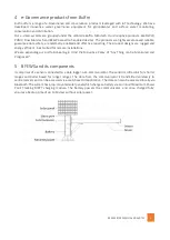
It comprises of a sensor connected to a data logger-cum-communicator. The sensor is Ultrasonic for shorter 

ranges and  Radar based  for longer ranges. The data from the communicator is  transmitted wirelessly  to 
central servers and can be accessed via a web-based UI application. The data can also be accessed locally via 

Bluetooth. The system has a top-mounted solar panel which charges a battery via an in-built Maximum Power 

Point  Tracking  MPPT  charging  module.  The  battery  powers  the  communicator,  and  once  charged  fully, 
ensures a backup time of up to 10 days without solar power. 


Summary of Contents for BFEWS-IRT

Page 1: ...WS IOM MANUAL R0 160721 1 Installation Operation Maintenance Manual Bulfro Flood Early Warning System BFEWS Bulfro Monitech Pvt Ltd Flat No 2 Janai Apartment Behind Vedvihar Kothrud Pune 411038 MH Ind...

Page 2: ...configuration typical installations 5 6 2 Remote configuration typical installation 5 7 Specifications 6 7 1 BFEWS options 6 7 2 BFEWS models 6 7 3 BFEWS Technical specifications 6 8 Mechanical dimen...

Page 3: ...lakes and rivers which lie close to or pass through a city The system is telemetry enabled which wirelessly communicates with the control station servers of the local governing bodies Data from BFEWS...

Page 4: ...are rugged and energy efficient best suited for remote installations We are expanding our portfolio bearing in mind the Disruptive Policy of Any Thing can be Monitored and Prognosed 5 BFEWS and its co...

Page 5: ...ousing the Communicator battery and the solar panel is mounted remotely The Communicator and Sensor are interconnected via a signal cable Note The illustrations depicted below represent few of the typ...

Page 6: ...rger Ambient temperature and pressure sensor Boom mounted components Sensor Ingress Protection rating IP56 IP65 Dimensions Mounting base 300x300 mm square Pole height 750 to 1200 mm site dependent Pol...

Page 7: ...6 Hz Ingress Protection rating IP67 Wetted parts Aluminium with oxidized surface PVC silicone rubber Radar sensor option VEGAPULS C 21 Range 0 to 15 m Deviation 2 mm Signal Output 4 20 mA Operating f...

Page 8: ...em ordered Stand pole Boom with sensor Antenna Communicator Battery module with battery and MPPT charger Solar panel Mechanical accessories Inspect each package for any in transit damage to the packin...

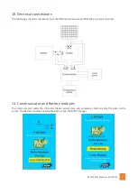
Page 9: ...tic represents how the different components of BFEWS are interconnected 11 Communicator and Battery modules The communicator reads the Ultrasonic Radar sensor data and wirelessly communicates the data...

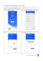
Page 10: ...at the time of installation during troubleshooting and maintenance Click on the BFEWS application and log in using your Username and Password Enable Bluetooth on your Smartphone Connect to Communicat...

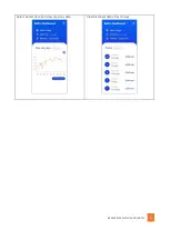
Page 11: ...BFEWS IOM MANUAL R0 160721 11 Select earlier date and view previous data View historical data of last 5 days...

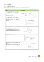
Page 12: ...positions Keep stand pole away Drill holes Hammer in grouting bolts Fix boom to stand pole using 8 M10 size Allen bolts Fix sensor to sensor holder Pass sensor cable through boom This will later conn...

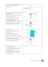
Page 13: ...tery modules Make all connections in accordance with the chapter Electrical connections Turn on switch Check system status using LEDs on communicator These LEDs indicate status of communicator power a...

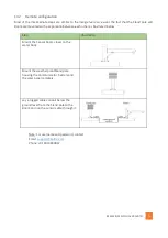
Page 14: ...tween each other as illustrated below Step Illustration Mount the Sensor boom closer to the water body Mount the weatherproof Stand pole housing the Communicator battery and the solar panel remotely L...

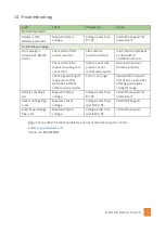
Page 15: ...onnected properly Mount and connect Antenna properly Check signal strength range on a mobile which has a SIM of same service provider Poor or no range Replace SIM card with that of service provider of...

Reviews: