background image

11 


S

TATUS 

&


A

LERTS


O

VERVIEW

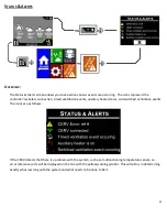
The Status & Alerts screen allows you to see when various events are occurring.  The icons represent the 
controller’s wireless connection, timed ventilation events, auxiliary heater status, and switched ventilation events.  
The icons are as follows: 


If the CERV detects that there is a problem with the system, such as a malfunctioning temperature sensor, an 
error reference code will be displayed on the line with the yellow warning symbol.  This will aid us in determining 
exactly what is wrong with the system and what needs to be done to fix it. 

Summary of Contents for CERV

Page 1: ...1 CERV WIRELESS TOUCHSCREEN CONTROLLER USER S MANUAL REVISION 1 1 11 06 13 BUILD EQUINOX 1103 N HIGH CROSS RD URBANA IL 61802 1 773 492 1893 USER S MANUAL...

Page 2: ...k up electric duct heater and the wireless ventilation switches The touchscreen interface was designed from the ground up to be simple and intuitive retaining a high degree of usability without having...

Page 3: ...n event may have been started or the CERV may have simply decided that it is more efficient to heat or cool the home with outside air If the home is within the heating and cooling setpoints but the CE...

Page 4: ...oling setpoints for the CERV Please see the following figure for an explanation of how the setpoints work The check box will submit your changes to the CERV while the X will cancel the changes made to...

Page 5: ...ate that a home may have bad odors as well as negative effects on productivity alertness and general comfort In the case that the CO2 and VOC sensors do not pick up specific elements that you may be s...

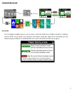
Page 6: ...can choose to force the CERV into a ventilation mode for a specified amount of time Say you know you are going to be cooking or producing a high amount of humidity you may decide to have the CERV sta...

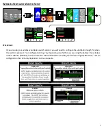
Page 7: ...onfigure the ventilation length for when the switch is pressed Your configuration may vary depending on whether you are using the battery free wireless rocker switches PTM265 or the transmitter wired...

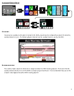
Page 8: ...following figure indicates how the auxiliary heater is used by the CERV RECOMMENDATIONS The auxiliary heater setpoint is limited as to always be below the CERV s heating setpoint This means that the...

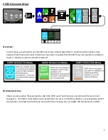
Page 9: ...may only operate in ventilation mode or that the system should just remain off RECOMMENDATIONS Unless you are positive that you need to switch the CERV out of Auto mode we recommend that you do not c...

Page 10: ...onfigure the auto off feature of the screen If there has been no interaction with the screen after the amount of time specified in Display Timeout the touchscreen controller will disable the screen to...

Page 11: ...ents auxiliary heater status and switched ventilation events The icons are as follows If the CERV detects that there is a problem with the system such as a malfunctioning temperature sensor an error r...

Reviews: