


CU-EMA+
9 Appendices
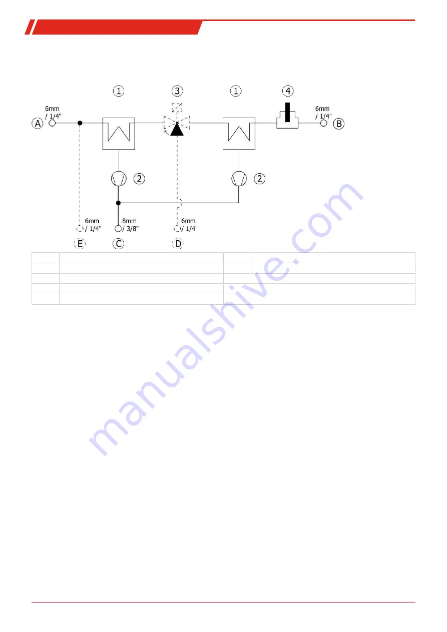
9.1 Flow Diagram
A Sample gas input
1 Cooler unit
B Sample gas output
2 Condensate pumps
C Condensate output
3 Solenoid valve for adding test gas (optional)
D Test gas input (optional)
4 Moisture detector
E Instrument air input (optional)
29
Bühler Technologies GmbH
BE440029 ◦ 10/2020


