87) to lapping handle. Assemble guide sleeve to sprocket
shaft bearing bushing. Sleeves, for use with tapered
bearing, are assembled to case with bearings and small
spacer collar. Finger-tighten the sleeve parts.
3.
Insert lap shaft with arbor assembled through pinion
bearing bushing and into guide sleeve. Tighten arbor
expansion collars using a length of 0.156 in. (3.962 mm)
rod as spanner until arbor begins to drag. Do not adjust
arbor snug in bushing or bushing will develop a condition
where hole is larger at ends than it is in the center.
4.
Withdraw arbor far enough to coat lightly with 220 grit
lapping compound. Do not apply a heavy coat.
5.
Reposition lap in bushing and turn handle at moderate
hand speed. Work lap back and forth in bushing, as it is
revolved, to avoid grooving and tapering.
6.
At frequent intervals, remove lap from crankcase, wash
and inspect bushing. Lapping is completed when entire
bushing surface has a dull, satin finish rather than a glossy,
smooth appearance. If necessary, flush off lap in cleaning
solvent, air dry and apply fresh, light coat of fine lapping
compound.
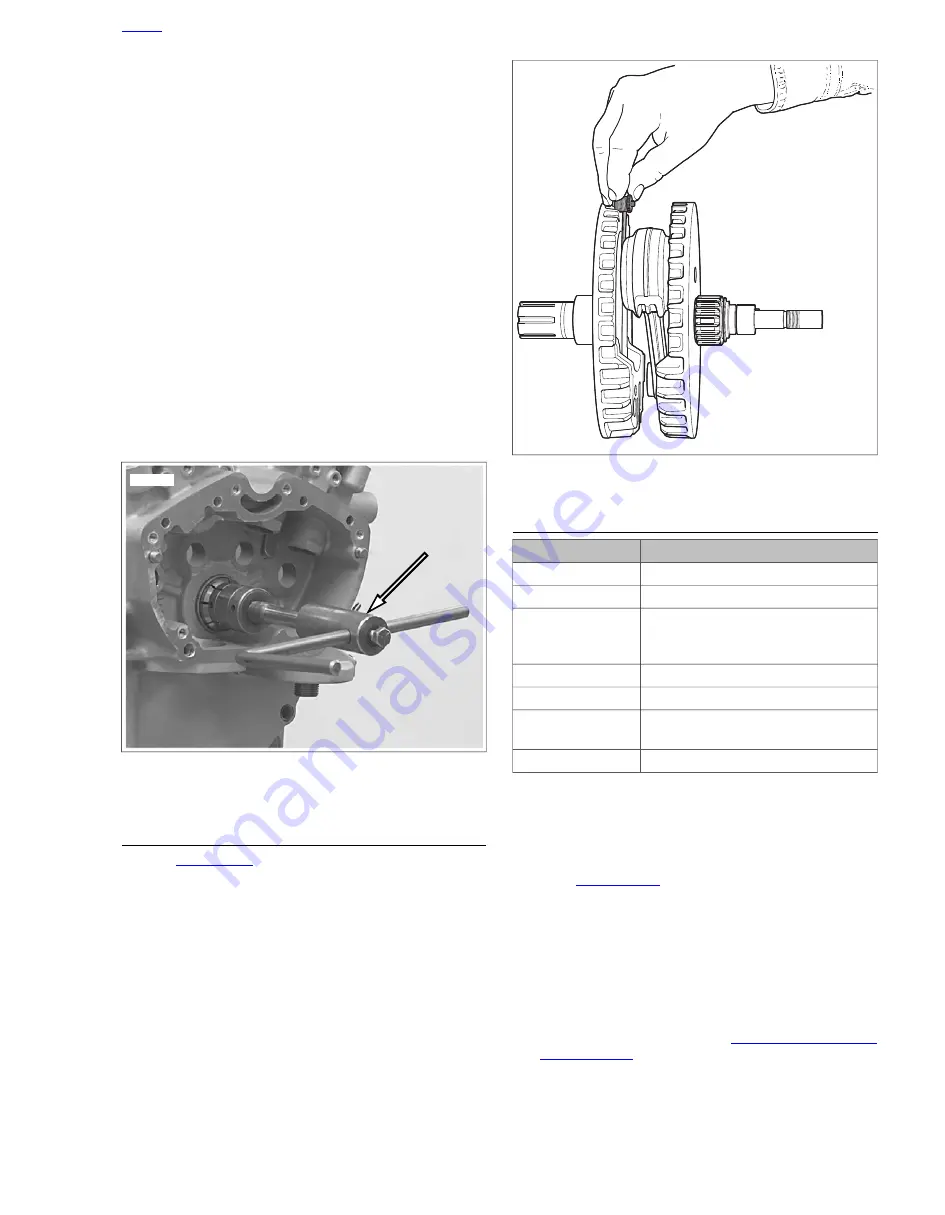
sm02983
Figure 3-132. Lapping Pinion Shaft Bearing Outer Race
with Crankcase Main Bearing Lapping Tool
CHECKING CONNECTING ROD SIDE PLAY
1.
. Check connecting rod side play with a
thickness gauge as shown.
2.
If side play measurement is greater than the service wear
limit, 0.036 in. (0.8 mm), replace the flywheel/connecting
rod assembly.
sm02984
Figure 3-133. Checking Connecting Rod Side Play
ASSEMBLY
TOOL NAME
PART NUMBER
SPROCKET SHAFT ADAPTER
B-42579-6
COLLAR
B-42579-7
CRANKCASE BEARING
REMOVER/INSTALLER WITH
ADAPTER
B-45655, HD-42720-
2 AND HD-46663
SPROCKET SHAFT SEAL INSTALLER
B-45676-A
CRANKSHAFT GUIDE
HD-42326-B
SPROCKET SHAFT BEARING
INSTALLER
HD-42579
COLLAR
HD-97228-55A
Crankcase Halves
NOTE
Lubricate all parts with Harley-Davidson 20W50 engine oil, and
proceed as follows:
1.
See
. Using CRANKCASE BEARING
REMOVER/INSTALLER WITH ADAPTER (Part No. B-
45655, HD-42720-2 and HD-46663), install sprocket shaft
bearing into left crankcase half from the inside.
NOTE
Make sure that the bearing assembly bottoms against the
machined shoulder in the left crankcase half.
2.
Install new bearing retaining ring (3) in left crankcase half.
3.
Install transmission. See
2010 XB Service: Engine 3-91
Summary of Contents for XB 2010
Page 1: ...2010 Buell XB Models Service Manual 99490 10Y 2009 Buell Motorcycle Company ...
Page 4: ...Blank Text Here ...
Page 6: ...NOTES ...
Page 22: ...NOTES ...
Page 78: ...1 56 2010 XB Service Maintenance NOTES ...
Page 80: ...NOTES ...
Page 268: ...NOTES ...
Page 306: ...sm00134 Figure 3 46 Valve Spring Compressor HOME 3 38 2010 XB Service Engine ...
Page 338: ...sm00207 Figure 3 98 Flanged Oil Line HOME 3 70 2010 XB Service Engine ...
Page 364: ...3 96 2010 XB Service Engine NOTES ...
Page 366: ...NOTES ...
Page 410: ...4 44 2010 XB Service Fuel System NOTES ...
Page 412: ...NOTES ...
Page 472: ...5 60 2010 XB Service Drive Transmission NOTES ...
Page 474: ...NOTES ...
Page 488: ...sm00366 Figure 6 13 Boot Gap HOME 6 14 2010 XB Service Electrical ...
Page 570: ...6 96 2010 XB Service Electrical NOTES ...
Page 572: ...NOTES ...
Page 596: ...NOTES ...
Page 610: ......
Page 620: ...B 24 2010 XB Service Appendix B Wiring NOTES ...
Page 622: ...NOTES ...
Page 626: ...C 4 2010 XB Service Appendix C Conversions NOTES ...
Page 628: ...NOTES ...
Page 666: ...D 38 2010 XB Service Appendix D Hose and Wire Routing NOTES ...
Page 668: ...NOTES ...
Page 674: ...E 6 2010 XB Service Appendix E Active Intake Japanese Models NOTES ...
Page 675: ...TABLE OF CONTENTS SUBJECT PAGE NO F 1 GLOSSARY F 1 APPENDIX F GLOSSARY ...
Page 676: ...NOTES ...
Page 680: ...F 4 2010 XB Service Appendix F Glossary NOTES ...
Page 706: ...XXVI TORQUE VALUES NOTES ...


