Important notes
Indications importantes
Wichtige Hinweise
System
Notes for the user and installer
Our termination systems and patch products for the generic cabling meet the currently valid
standards EN 50173-1:2002 and IEC 60603-7.
The user or installer has to check and take care to use solely patch and termination cables that
meet the EN-/IEC standards when completing the installation. If necessary ask your supplier to
certify that the installed cables and plugs meet the standards. The use of products that do not
comply with the above-mentioned standards may cause malfunctions and affect performance.
Indications pour utilisateurs et installateurs
Nos systèmes de raccordement et produits de distribution pour le câblage générique sont con-
formes aux normes en vigueur EN 50173-1:2002 et IEC 60603-7.
Il est nécessaire que l’utilisateur ou l’entreprise d’installation vérifient et tiennent compte
d’employer uniquement les câbles de distribution et de raccordement qui répondent aux
normes EN-/IEC. Il est conseillé de se faire certifier cette conformité aux normes par le fournis-
seur des câbles et fiches utilisés. L’utilisation de produits qui ne sont pas conformes aux normes
ci-dessus peut causer des perturbations des fonctions ou de la performance.
Hinweis für Verwender und Monteure
Unsere Anschlusssysteme und Verteilerprodukte für die strukturierte Gebäudeverkabelung
entsprechen den gültigen Normen EN 50173-1:2002 und IEC 60603-7.
Bei Komplettierung der Anschlüsse muss der Verwender/Montagebetrieb prüfen und beachten,
dass nur Patch- und Anschlusskabel, die die EN-/IEC-Normen erfüllen, verwendet werden.
Lassen Sie sich ggf. vom Lieferanten den Nachweis geben, dass die eingesetzten Kabel und
Stecker der Norm entsprechen. Die Verwendung von Produkten, die nicht den vorstehenden
Normen entsprechen, können Funktions- und Leistungsstörungen zur Folge haben.
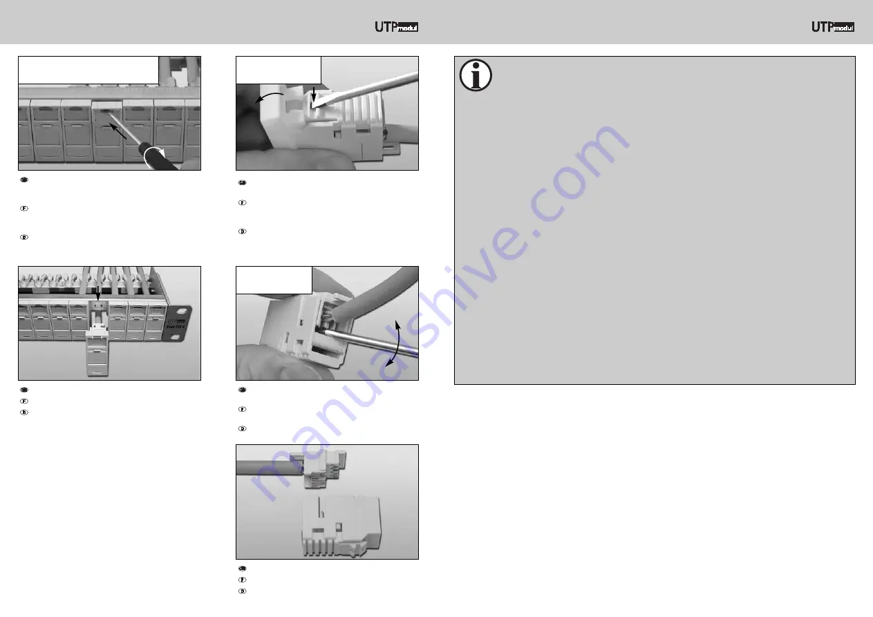
Carefully lever out the loader from the back of the
module...
Décrocher la pièce d’installation à l’arrière avec
précaution...
Das Ladestück auf der Rückseite des Moduls vor-
sichtig aushebeln...
...and separate the two parts of the housing.
...et détacher les deux parties du boîtier.
...und beide Gehäuseteile voneinander trennen.
System
Disassembling individual components
Démontage des différents éléments
Demontage der einzelnen Komponenten
Pull the unit out of the frame.
Retirer l’unité du support.
Einheit aus dem Tragrahmen herausziehen.
Press the clamping strip at the bottom of the module
down with a screw driver and remove the module unit.
Appuyer avec un tournevis sur la plaquette de
verrouillage, côté inférieure du module et enlever
l’unité de module.
Klemmleiste auf der Unterseite des Moduls mittels
Schraubendreher eindrücken und Modulaufnahme
abnehmen.
To release a module unit open the label window,
insert a flat bladed screw driver into the upper
opening and twist.
Pour déverrouiller une unité de module ouvrir la
fenêtre à étiquette, ensuite introduire un tournevis
plat dans l’ouverture en haut et le tourner.
Modulaufnahme entriegeln, hierzu Sichtfenster öff-
nen und einen flachen Schraubendreher in die obere
Öffnung schieben und drehen.
Unbolt a module faceplate
Décrocher une couverture de module
Lösen der Modulaufnahme
Removing a module
Décrocher un module
Lösen des Moduls
Opening a module
Ouvrir le module
Öffnen des Moduls


