background image

4

Living Now with Netatmo

Installation Manual

General features

The Gateway allows you to create your Smart electric system by associating together all the 
connected devices of the Living Light with Netamo range and light relays. 
Supplied as standard is also the wireless master IN&OUT scenario control, item L/N/NT4570CW, 
required for the association of all the connected devices and for the activation of the “IN” and 
“OUT” scenarios. 
The Gateway connects to your home router through the Wi-Fi connection (2.4GHz only), to allow 
the local or remote control of lights, controlled sockets and rolling shutters using the smartphone 
(“

Home + Control

” App) or voice commands (using a voice assistant). 

In order to optimize signal reception, it is recommended that the Gateway is installed close to the 
router.

Note

: not all the products shown in this manual are available for all markets. 

Check the availability of the same from your supplier or installer.
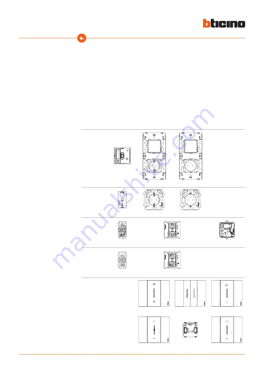
Gateway

K4500C

KG/KW/KM4501C

KG/KW/KM4502C

Connected 

socket

K4531C

KG/KW/KM4141C

KG/KW/KM4142C

Connected 

light switch/

light relay

ZLD15

K4411CM2

RF

L

N
N

µ

1.3A max

0.4A max

ON

OFF

100-240V

50Hz/60Hz

Made in

China

ZLS26     

K4003C

K4411CM2

3584C

Shutters


ZLSH06

K4027CM2

K4027C

K4027CM2

Radio controls

K4003CW

K4003DCW

K4570CW

1

2

K4027CW

3577C

K4574CW

Summary of Contents for Living Now with Netatmo

Page 1: ...Installation Manual www bticino com Living Now with Netatmo...

Page 2: ...Living Now with Netatmo Installation Manual...

Page 3: ...mo 5 Associate the connected devices 9 Add a connected device 15 Add a wireless scenario control 17 Associate a wireless light rolling shutter control to one or more modular connected devices 20 Disso...

Page 4: ...e control of lights controlled sockets and rolling shutters using the smartphone Home Control App or voice commands using a voice assistant In order to optimize signal reception it is recommended that...

Page 5: ...nstallation Manual Install Living Now with Netatmo Check that the system is not powered It is now possible to connect all your system devices as per the following diagrams OFF 1 Disconnect the voltage...

Page 6: ...K4531C Connected2 module shuttercontrol K4027CM2 AS AN ALTERNATIVE Connected dimmer K4411CM2 providedwith K4411CM2 Compensator Gateway KG KW KM4502C Gateway KG KW KM4501C Connected two way switch K40...

Page 7: ...Now with Netatmo Installation Manual 1 2 Check that the LEDs of all the devices turn on red steady with the exception of the wireless LEDs which will be off ON 2 Reconnect the power using the general...

Page 8: ...ciate all the devices and take advantage of the connected functions of your system Note connected sockets will be powered by default After installing the Smart electric system it will be possible to l...

Page 9: ...anual 1 2 Associate the connected devices Wait 1 minute for correct system start up after which complete the following association procedure within 15 minutes from powering If this time is exceeded di...

Page 10: ...release one of the control keys the LED flashes green release it and wait for the LED to turn off Note after re powering the system always wait at least one minute K4570CW Master wireless In Out scen...

Page 11: ...sociation press and hold down the two control keys at the same time the LED will turn green the LED switches off K4570CW Master wireless In Out scenario control K4500C Gateway The Gateway LED goes fro...

Page 12: ...procedure will end automatically Check that the LEDs of all the devices turn green steady with the exception of the wireless LEDs which will be off 5 End the association press and release the two con...

Page 13: ...the LEDs of all the devices immediately turn off the connected devices are now associated with each other 1 2 Note if the LEDs of any devices stay red disconnect the power from the system reconnect i...

Page 14: ...l Note the K4574CW wireless scenario control is preset for controlling Night and Day scenarios It is then possible to define the actions that will perform these scenarios using the Home Control App No...

Page 15: ...een completed follow the instructions of the Add a product to this home menu in the App or Add a connected device 1 Disconnect the voltage from the general switch 2 Install the new connected device OF...

Page 16: ...procedure will suggest exactly the same sequence of actions described here Check that the LEDs of all the devices are off with the exception of the device to add which must have a steady red LED 4 Com...

Page 17: ...ss and hold down the two control keys at the same time the LED will turn green Release the keys and wait until it turns off K4570CW Master wireless In Out scenario control 1 1 Check that the LEDs of a...

Page 18: ...and wait for the LED to turn off 5 End the association press and release the two control keys at the same time The LED will start flashing green wait until it turns off K4570CW Master wireless In Out...

Page 19: ...vices immediately turn off The control is now associated to your Smart electric system and you will be able to control the IN OUT and or Day Night scenarios You can also add light control K4003CW K400...

Page 20: ...e association press and hold down the two control keys at the same time the LED will turn green Release the keys and wait until it turns off Check that the LEDs of all the devices immediately turn gre...

Page 21: ...l or K4027CW wireless shutter control 3 Fit the cover and the plate on the wireless control Warning if cover and plate are not fitted do not press the wireless control keys 4 Press and release one of...

Page 22: ...1 K4003CW K4003DCW 3577C wireless light control or K4027CW wireless shutter control 1 The LEDs flash three times blue Release the wireless control The control LED goes from blue flashing to off turns...

Page 23: ...d device to associate 6 Table A Association of the connected devices wireless controls Wireless controls Connected devices that can be controlled K4003DCW K4003CW 3577C Lights K4003C K4411CM2 3584C K4...

Page 24: ...flashing to off turns on again blue for a second and then turns off The LED of the connected device goes from blue flashing to green then turns back to blue for one second and then again to green 7 E...

Page 25: ...ation Manual Check that the LEDs of all the devices immediately turn off the association has been completed correctly Repeat the procedure shown for each wireless control point from which you wish to...

Page 26: ...then turns off 1 1 Procedure for wireless controls K4003CW K4570CW K4003DCW K4574CW 3577C wireless light control or K4027CW wireless shutter control 2 2 Warning this procedure completely dissociates t...

Page 27: ...reset pushbutton The LED flashes blue then it goes off then turns red Now release the pushbutton The LED turns red steady K4003C 3584C K4411CM2 K4027C K4027CM2 K4027C K4027CM2 K4531C KG KW KM4441AC KG...

Page 28: ...nd all rolling shutters go down control lights sockets and rolling shutters with their wireless controls Download the Home Control App and configure it so that all the other functions of the Smart ele...

Page 29: ...29 Living Now with Netatmo Installation Manual...

Page 30: ...Spa reserves at any time the right to modify the contents of this booklet and to communicate in any form and modality the changes brought to the same BTicino SpA Viale Borri 231 21100 Varese www btic...

Reviews: