XL SERIE BSTDJ.COM
© Copyright LOTRONIC 2012
Page 10
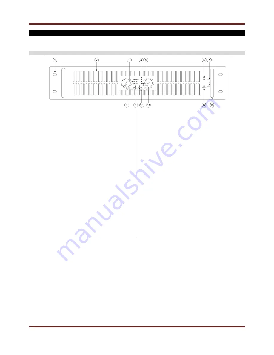
DESCRIPTION
FRONT PANEL
1. INSTALLATION
SOCKET
Use to fix when install to the rack.
2. AIR
ENTRANCE
This part is the air entrante. Don't obstruct it.
3. CLIP
LED
When this indicator 1s on, it means the amplifier has reached
its maximum output power (CLIP). The distortion is about
0.5%. Then you need to turn down the input signal to make
sure the amplifier work under low distortion.
4. PROTECTION
LED
When this indicator is illumed, it means the amplifier is on the
protection status, includes output short circuit, over-heat, DC,
VHF, constant non-music high frequency signal (self-excitation
or long time whistle).
5. SIGNAL
LED
When this indicator on, it means the output port of the amplifier
already has signal, and the sensitivity is about 0.35V.
6. ON
LED
When this indicator is on, it means the main power supply
system of amplifier has been working. Otherwise, it is
opposite.
7. POWER
SWITCH
This switch is used for power on and off. Press the upper part
to switch on, and lower part to switch off.
8. CH1 VOLUME CONTROL
In bridge mode, this potentiometer controls two channels
volume, the CH2 potentiometer invalid.
In stereo or parallel mode: this potentiometer just controls CH1
volume. Gain control range: -80dB / 0dB, available turning
angle is 280 degree.
9. PARALLEL
LED
While this indicator lights, the amplifier is on parallel mode.
10. BRIDGE LED
While this indicator illumed, the amplifier is on bridge mode.
11. CH2 VOLUME CONTROL
In bridge mode, this potentiometer invalid, the volume is
controlled by CH1 potentiometer.
In stereo or parallel mode, the potentiometer just controls
CH2 volume. Gain control range: -80dB / 0dB, available
turning angle is 280 degree.
12. POWER LED
While connect the power cable of the equipment, this
indicator lights, until the power switch turn to ON, the power
ON indicator illuminated, then this indicator extinguish.
13. HANDLES


