LAB10-R
BSTDJ.COM
© Copyright LOTRONIC 2016
Page 3
DESCRIPTION
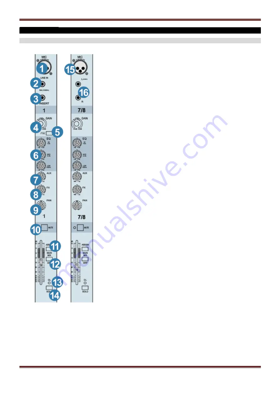
CHANNEL CONTROL SECTION
1. MIC INPUT
This balanced input is a XLR input.
Pin 1 = ground
Pin 2 = + ( Hot point )
Pin 3 = - ( Cold point )
This input can work with electret microphone (See phantom button).
Note
: Switch the mixer off before to enable the phantom power.
2. LINE INPUT
This jack input is provided for use of a balanced or unbalanced source connection,
CD player, MP3, deck, turntable, keyboard,..
Note
: Do not connect XLR and Jack socket in the same time
3. INSERT CHANNEL
These unbalanced jacks are for connection serial effects processors such as compressors, equalizers,
de-essers or filters. The inser
t point is after the gain control and low cut filter, but before the channel’s EQ
and level.
The channel signal can go out of the inset jack to an external device, be processed and come back in on
the same insert jack. To do this requires a standard insert cable that must be wired thusly.
Tip = send (output to effects device)
Ring = return (input from effects device)
Sleeve = common (Ground)
4. GAIN CONTROL
Use to adjust sensitivity on input signal from +15dB to -45dB.
5. LOW CUT SWITCH
All mono channels have a low-cut switch that cuts bass frequencies below 75Hz at a rate of 18dB per
octave. We recommend that you use low-cut on every microphone application except kick drum, bass
guitar or bassy synth patches.
6. CHANNEL EQUALIZATION (EQ)
HIGH LEVEL
This control gives you up to 15db boost or cut at 12KHz. This circuit is flat (no boost or cut) at center
detent position.
MID LEVEL
This control gives you up to 15db boost or cut at 400Hz and 2,5KHz. This circuit is flat (no boost or cut)
at center detent position.
LOW LEVEL
This control gives you up to 15db boost or cut at 80Hz. This circuit is flat (no boost or cut) at center
detent position
7. AUX MON CONTROL
These knobs tap a portion of
each channel’s signal to set up a nice monitor mix feeding stage monitors,
independent of the main mix. The controls are off when fully turned down, delver unity gain at the center
detent and can provide up to 15dB gain turned fully up.
8. FX AUX SEND
These controls allow you set up two independent mixes for the internal or external effects processors.
The controls are off when fully turned down, delver unity gain at the center detent and can provide up to
15dB gain turned fully up.
9. PAN CONTROL
The pan control sends continuously variable amounts of the post fader signal to either the left or right
main busses. In the center position, equal amount of signal are sent to the left and right busses.
10. MUTE BUTTON
All output from the channel are enabled when the mute switch released and muted when the switch is
down
11. ASSIGN SWITCH
Alongside each channel fader are there buttons referred to as channel assignment switches. Used in
conjunction with the channel’s pan knob, they are used to determine the destination of the channel’s
signal.
12. MAIN MIX
Press this switch in to listen to the main mix in your control room and headphones, and to check the main
mix levels in the meters. In addition to the main mix, you can listen to any combination of tape. If the
assign to main mix switch is engaged, you cannot hear the main mix in the control room or headphones,
or see its level on the meters, this is prevent feedback caused by sending the main mix to the main mix.
13. OL LED
The OL (Over Load) LED
will come on when the channel’s input signal is too high. This should be
avoided, as distortion will occur. If the OL LED comes on regularly, check the gain control is set correctly
for your input device and that the EQ is not set with too much boost.
14. SOLO
Whenever a solo switch is engaged, you’ll only hear the soloed channel(s) in the headphones. This gives
you the opportunity to audition the channels before they are added to the main mix. You can also use
solo to set the gain of each channel correctly.
15. XLR INPUT ( STEREO CHANNELS)
These inputs are balanced XLR inputs.
16. LINE INPUT JACKS( STEREO CHANNELS)
These inputs are unbalanced phone-jack stereo inputs.


