2 0
Rear Barrier Strip
13.0
Rear Barrier Strip
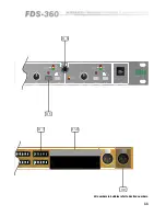
The barrier strip located on the rear of the
FDS-360
provides for a number of
facilities specific to the BSS
FDS-360
, to give the operator greater flexibility.
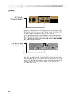
By adding a wire link between the two marked terminals all four limiters can
be cancelled and taken out of circuit. Simultaneously the four red LEDs
marked 'over' on the front panel will illuminate, regardless of the level of the
input signal, to give a warning to the operator that the limiters have been
cancelled.
13.1 Limiter Cancel
As mentioned in section 11.1, 'Mode Switch', when the unit is switched on all
four mute circuits will operate to protect the following equipment from
potentially dangerous DC thumps. To commence using the
FDS-360
the mutes
will then have to be operated via the respective mute switches. In certain
fixed installations where access to the
FDS-360
is not possible by the operator,
it will be necessary to activate the auto-mute cancel facility by adding a wire
link between the two marked terminals. Once activated, the
FDS-360
will
still power-up in the mute mode, thus maintaining protection, but after
approximately 20 seconds will automatically un-mute itself to allow full
operation to commence.
13.2 Auto Mute
Cancel
As mentioned in section 11.7, 'Limiter Threshold Switch', the limiter threshold
reference is +10dBv. Should a threshold below -5dBv be required, adding a
wire link between the two marked terminals will reduce the reference to
+4dBv, thus allowing a lower threshold point of -11dBv. This operates on all
four limiters together. However, the adjustable range of 15.5dB down from the
reference level allows sufficient adjustment for each individual limiter for
correct speaker protection.
Refer to section 15
for further information.
13.3 Limiter
Threshold
Reference
13.4 Band Insertion
Points
The barrier strip provides 'send' and 'return' points for each of the four bands
individually. This allows the operator to connect external equipment such as
equalisers and digital time delays into the particular frequency band required.
The send or input to the external equipment or return to the
FDS-360
is taken
to the appropriate BAND IN terminal. The factory provided wire link should
obviously be removed. Both the inputs and outputs from the barrier strip are
unbalanced and work at line level with a headroom of +20dBv.
Summary of Contents for FDS 360
Page 1: ...1 FDS 360 User Manual...
Page 51: ...51 User Notes...
Page 52: ...52 User Notes...
Page 53: ...53...
Page 54: ...54 User Notes...

