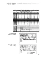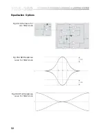
1 8
.5
1
2
4
8 dB
ON
OFF
WATS560B
4H
.5
1
2
4
8 dB
ON
OFF
WATS560B
4H
.5
1
2
4
8 dB
ON
OFF
WATS560B
4H
.5
1
2
4
8 dB
ON
OFF
WATS560B
4H
Controls
11.7 Limiter
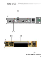
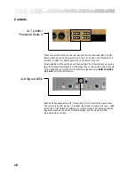
Threshold Switch
These four switch blocks on the rear panel allow the individual band limiter
thresholds to be set. With all switches in the 'out' position, the threshold will
be 10dBv or +4dBv depending on the barrier strip link.
Binary addition of the switches will then subtract from this reference to give a
specific threshold adjustable in 0.5dB steps. (The centre switch position should
not be used and is provided for manufacturing reasons only).
Refer to section
13.1 & 15
for further information.
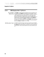
11.8 Signal LEDs
Each band has associated with it three LEDs which monitor the signal level.
The lower green LED gives an indication that signal is present at a level -15dB
below the limiter threshold setting. The middle orange LED indicates that the
signal has reached the limiter threshold setting, and the upper red LED
indicates 6dB of limiting.
Summary of Contents for FDS 360
Page 1: ...1 FDS 360 User Manual...
Page 51: ...51 User Notes...
Page 52: ...52 User Notes...
Page 53: ...53...
Page 54: ...54 User Notes...

