background image

577C--C, 577C--E, 577C--F: Installation Instructions

Manufacturer reserves the right to change, at any time, specifications and designs without notice and without obligations.

48

A08505

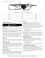
Fig. 28 – Fan Blade Position

Refrigerant Circuit 

Annually inspect all refrigerant tubing connections.

If low cooling performance is suspected, leak-test all refrigerant tubing

using an electronic leak-detector or liquid-soap solution. If a refrigerant

leak is detected, refer to the Check for Refrigerant Leaks section. 
If  no  refrigerant  leaks  are  found  and  low  cooling  performance  is

suspected,  refer  to  the  Checking  and  Adjusting  Refrigerant  Charge

section. 

Gas Input 

The  gas  input  does  not  require  checking  unless  improper  heating

performance  is  suspected.  If  a  problem  exists,  refer  to  the  Start-Up

section. 

Evaporator Airflow 

The  heating  and/or  cooling  airflow  does  not  require  checking  unless

improper performance is suspected. If a problem exists, be sure that all

supply- and return-air grilles are open and free from obstructions, and

that the air filter is clean. When necessary, refer to the Indoor Airflow

and Airflow Adjustments section to check the system airflow. 

Puron Items

The  indoor  metering  device  is  either  a  TXV  or  orifice  type  device

depending on size. 

Pressure Switches 

Pressure switches are protective devices wired into control circuit (low

voltage). They shut off compressor if abnormally high or low pressures

are  present  in  the  refrigeration  circuit.  These  pressure  switches  are

specifically  designed  to  operate  with  Puron  (R-410A)  systems.  R-22

pressure  switches  must  not  be  used  as  replacements  for  the  Puron

(R-410A) system. 

Low Pressure Switch (24 and 30 size only) 

This  switch  is  located  on  the  suction  line  and  protects  against  low

suction pressures caused by such events as loss of charge, low airflow

across  indoor  coil,  dirty  filters,  etc.  It  opens  at  50

  psig.  If  system

pressure is above this, switch should be closed. To check switch: 

1. Turn off all power to unit. 
2. Disconnect leads on switch. 
3. Apply ohm meter leads across switch. You should have continuity

on a closed switch.

NOTE: 

Because  these  switches  are  attached  to  refrigeration  system

under  pressure,  it  is  not  advisable  to  remove  this  device  for

troubleshooting unless you are reasonably certain that a problem exists.

If switch must be removed, remove and recover all system charge so that

pressure  gauges  read  0  psig.  Never  open  system  without  breaking

vacuum with dry nitrogen.

High-Pressure Switch

The high-pressure  switch  is located  in  the  discharge line and  protects

against excessive condenser coil pressure. It opens at 650 psig.
High pressure may be caused by a dirty outdoor coil, failed fan motor, or

outdoor air recirculation. To check switch: 

1. Turn off all power to unit. 
2. Disconnect leads on switch. 
3. Apply ohm meter leads across switch. You should have continuity

on a closed switch.

Compressor (Puron Refrigerant)

The compressor used in this product is specifically designed to operate

with Puron (R-410A) refrigerant and cannot be interchanged. 
The compressor is an electrical (as well as mechanical) device. Exercise

extreme caution when working near compressors. Power should be shut

off,  if  possible,  for  most  troubleshooting  techniques.  Refrigerants

present additional safety hazards.

Max Distance Between Top of Fan Grille and Bottom of Fan Blade

Size

“A”

IN.

mm

24

9.0

228

30

7.1

1804

36

8.0

203

42

7.6

193

48

7.6

193

60

7.6

193

MOTOR

FAN GRILLE

MOTOR SHAFT

A

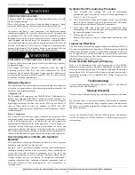
WARNING

!

EXPLOSION, SAFETY AND ENVIRONMENTAL 

HAZARD

Failure to follow this warning could result in  personal injury, death or

property damage.

System  under  pressure.  Relieve  pressure  and  recover  all  refrigerant

before  system repair  or  final  unit  disposal.  Use  all service  ports  and

open all flow-control devices, including solenoid valves.

Summary of Contents for LEGACY 577C-C

Page 1: ...ential for personal injury Understand these signal words DAN GER WARNING and CAUTION These words are used with the safe ty alert symbol DANGER identifies the most serious hazards which will result in...

Page 2: ...s to the curb are required when using this kit 2 An alternative to the adapter curb is to modify the existing curb by removing the outer horizontal flange and use accessory kit number CPGSKTKIT001A00...

Page 3: ...on Prior to initial use and at monthly intervals all rigging shackles clevis pins and straps should be visually inspected for any damage evidence of wear structural deformation or cracks Particular at...

Page 4: ...7C C 577C E 577C F Installation Instructions Manufacturer reserves the right to change at any time specifications and designs without notice and without obligations 4 A200008 Fig 3 577C 24 36 Dimensio...

Page 5: ...7C C 577C E 577C F Installation Instructions Manufacturer reserves the right to change at any time specifications and designs without notice and without obligations 5 A190120 Fig 4 577C 42 60 Dimensio...

Page 6: ...ss 1 lb density Fig 5 Roof Curb Dimensions UNIT SIZE CATALOG NUMBER A IN mm B small common base IN mm B large base IN mm Part Number CPRCURB011B00 can be used on both small and large basepan units The...

Page 7: ...61 164 390 177 Rigging Weight 455 206 480 218 497 225 ACCESS PANELS MUST BE IN PLACE WHEN RIGGING PANNEAUX D ACCES DOIT TRE EN PLACE POUR MANIPULATION 50CY502286 2 0 CAUTION NOTICE TO RIGGERS PRUDENCE...

Page 8: ...17 4 7 3 17 4 7 INDOOR BLOWER Nominal Cooling Airflow CFM Size in Size mm Motor HP RPM 800 10x10 254x254 1 2 1050 800 10x10 254x254 1 2 1050 1000 10x10 254x254 1 2 1050 1000 10x10 254x254 1 2 1050 115...

Page 9: ...installations Table 1 Physical Data Continued UNIT SIZE 48090 48115 48130 60090 60115 60130 NOMINAL CAPACITY ton 4 4 4 5 5 5 SHIPPING WEIGHT lb SHIPPING WEIGHT kg 480 218 480 218 480 218 497 225 497 2...

Page 10: ...ll pipe 1 4 in 6 35 mm for every 15 ft 4 6 m of length to prevent traps Grade all horizontal runs downward to risers Use risers to connect to heating section and to meter 2 Protect all segments of pip...

Page 11: ...lation by removing duct covers 2 Select and size ductwork supply air registers and return air grilles according to American Society of Heating Refrigeration and Air Conditioning Engineers ASHRAE recom...

Page 12: ...ion Control Voltage Connections Do not use any type of power stealing thermostat Unit control problems may result Use no 18 American Wire Gage AWG color coded insulated 35 C minimum wires to make the...

Page 13: ...or shipping and handling damage such as broken lines loose parts disconnected wires etc b Inspect all field and factory wiring connections Be sure that connections are completed and tight c Ensure wir...

Page 14: ...inside of the control access panel to start the heating section NOTE Make sure that gas supply has been purged and that all gas piping has been checked for leaks A07679 Fig 11 Burner Assembly C99021...

Page 15: ...meter test dial to make one revolution 4 Divide number of seconds in Step 3 into 3600 number of seconds in one hr 5 Multiply result of Step 4 by the number of cubic feet cu ft shown for one revolutio...

Page 16: ...Installations from 2000 to 4500 ft 610 1372 m use U S A column 2001 to 3000 ft 611 to 914 m 0 to 2000 ft 0 610 m 2001 to 3000 ft 611 to 914 m 3001 to 4000 ft 915 to 1219 m 4001 to 5000 ft 1220 to 1524...

Page 17: ...F Installation Instructions Manufacturer reserves the right to change at any time specifications and designs without notice and without obligations 17 A150502 Fig 14 208 230 1 60 24 36 60 Size Connect...

Page 18: ...C F Installation Instructions Manufacturer reserves the right to change at any time specifications and designs without notice and without obligations 18 A150510 Fig 15 208 230 1 60 24 36 60 Size Ladde...

Page 19: ...7C F Installation Instructions Manufacturer reserves the right to change at any time specifications and designs without notice and without obligations 19 A200011 Fig 16 208 230 1 60 30 Size Connection...

Page 20: ...577C F Installation Instructions Manufacturer reserves the right to change at any time specifications and designs without notice and without obligations 20 A200012 Fig 17 208 230 1 60 30 Size Ladder W...

Page 21: ...E 577C F Installation Instructions Manufacturer reserves the right to change at any time specifications and designs without notice and without obligations 21 A150508 Fig 18 208 230 3 60 Connection Wir...

Page 22: ...C E 577C F Installation Instructions Manufacturer reserves the right to change at any time specifications and designs without notice and without obligations 22 A150511 Fig 19 208 230 3 60 Ladder Wirin...

Page 23: ...C E 577C F Installation Instructions Manufacturer reserves the right to change at any time specifications and designs without notice and without obligations 23 A150509 Fig 20 460 3 60 Connection Wirin...

Page 24: ...77C E 577C F Installation Instructions Manufacturer reserves the right to change at any time specifications and designs without notice and without obligations 24 A150512 Fig 21 460 3 60 Ladder Wiring...

Page 25: ...rners The blower motor continues to run until LS resets When the air temperature at the limit switch drops to the low temperature setting of the limit switch the switch closes and completes the contro...

Page 26: ...rom obstructions and adjusted properly This unit has independent fan speeds for gas heating and cooling modes Single phase models also have a dedicated continuous fan speed All models 1 phase and 3 ph...

Page 27: ...use of either a 24 VAC dehumidistat or a thermostat which includes control of a 24 VAC dehumidistat connection In either case the dehumidification control must open the control circuit on humidity ri...

Page 28: ...lower motor stops The unit is in a standby condition waiting for the next call for cooling from the room thermostat A14399 Fig 22 Single Phase IGC Board A09058 Fig 23 Interface Fan Board IFB DH DH DH...

Page 29: ...d 80 F 27 C dry bulb 67 F 19 C wet bulb indoor condition Where a dash appears do not attempt to check charge or charge unit under these conditions using the superheat method Weigh in method should be...

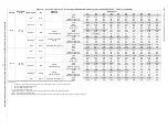
Page 30: ...Alternate Heating CFM 840 759 677 600 505 411 293 x x x BHP 0 14 0 15 0 16 0 16 0 17 0 17 0 18 x x x Gas Heat Rise F 53 NA NA NA NA NA NA NA NA NA Gas Heat Rise C 30 NA NA NA NA NA NA NA NA NA Medium...

Page 31: ...M 1223 1186 1151 1115 1075 1039 1001 957 914 870 BHP 0 34 0 34 0 35 0 36 0 37 0 37 0 38 0 39 0 40 0 41 Gas Heat Rise F 37 38 39 40 42 43 45 47 49 52 Gas Heat Rise o C 20 21 22 22 23 24 25 26 27 29 Med...

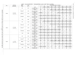
Page 32: ...d Cooling Alternate Heating CFM 1403 1358 1316 1265 1217 1167 1116 1067 1012 956 BHP 0 29 0 30 0 31 0 33 0 34 0 35 0 36 0 37 0 38 0 39 Gas Heat Rise F 48 50 51 53 56 58 61 63 NA NA Gas Heat Rise C 27...

Page 33: ...Cooling Alternate Heating CFM 1658 1622 1585 1549 1512 1476 1442 1402 1360 1322 BHP 0 39 0 40 0 41 0 42 0 44 0 45 0 46 0 47 0 48 0 49 Gas Heat Rise F 58 59 61 62 63 65 NA NA NA NA Gas Heat Rise C 32 3...

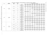
Page 34: ...A NA NA NA NA NA NA NA NA Med Low Pink CFM 1403 1361 1320 1276 1236 1192 1145 1099 1054 1012 BHP 0 28 0 29 0 30 0 31 0 31 0 33 0 34 0 35 0 36 0 37 Rise F NA NA NA NA NA NA NA NA NA NA Rise C NA NA NA...

Page 35: ...e oF NA NA NA NA NA NA NA NA NA Heating Rise oC NA NA NA NA NA NA NA NA NA Med Low Pink CFM 1136 1080 1015 957 912 861 808 723 633 Heating Rise oF 58 61 65 NA NA NA NA NA NA Heating Rise oC 32 34 36 N...

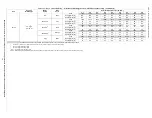
Page 36: ...34 Medium Red CFM 1736 1695 1642 1601 1553 1512 1465 1427 1381 Heating Rise o F 39 39 41 42 43 44 46 47 48 Heating Rise o C 21 22 23 23 24 25 25 26 27 Med High Orange CFM 2149 2111 2062 2026 1980 194...

Page 37: ...25 25 26 26 28 Medium Red CFM 1962 1915 1880 1843 1794 1753 1711 1675 1628 Heating Rise o F NA 35 36 36 37 38 39 40 41 Heating Rise o C NA 19 20 20 21 21 22 22 23 Med High Orange CFM 2131 2088 2065 2...

Page 38: ...1888 1860 1785 Heating Rise oF 45 46 46 47 48 49 50 51 53 Heating Rise oC 25 25 26 26 27 27 28 28 30 High Black CFM 2461 2409 2339 2286 2192 2140 2062 1968 1874 Heating Rise o F 39 40 41 42 43 44 46...

Page 39: ...16 17 18 19 20 20 22 23 25 27 High Black CFM 1560 1491 1416 1337 1255 1233 1160 1082 998 911 WATTS 708 699 683 674 660 634 624 606 581 566 BHP 0 76 0 75 0 73 0 72 0 71 0 68 0 67 0 65 0 62 0 61 Heatin...

Page 40: ...o F 29 31 33 35 34 36 38 40 42 45 Heating Rise o C 16 17 18 19 19 20 21 22 24 25 42090 35 65oF 19 36oC Low Blue CFM 952 882 806 746 671 605 530 551 486 435 WATTS 124 134 140 150 156 166 171 182 188 1...

Page 41: ...o F NA NA NA NA NA NA NA NA NA NA Heating Rise o C NA NA NA NA NA NA NA NA NA NA 48115 30 60oF 17 33oC Low Blue CFM 1503 1457 1423 1374 1330 1287 1241 1199 1153 1111 WATTS 225 233 246 254 269 282 292...

Page 42: ...o F 38 38 39 40 41 42 44 45 47 49 Heating Rise o C 21 21 22 22 23 23 24 25 26 27 60090 35 65oF 19 36oC Low Blue CFM 1479 1436 1387 1346 1298 1253 1206 1160 1114 1061 WATTS 224 239 247 262 270 284 300...

Page 43: ...BHP 0 24 0 26 0 26 0 28 0 29 0 30 0 32 0 33 0 34 0 35 Heating Rise oF 64 NA NA NA NA NA NA NA NA NA Heating Rise o C 36 NA NA NA NA NA NA NA NA NA Med Low Pink CFM 1841 1796 1761 1724 1690 1651 1616...

Page 44: ...SCFM 600 700 800 900 1000 1100 1200 1300 1400 1500 1600 1700 1800 1900 2000 2100 2200 600 1400 CFM 12x20x1 12x20x1 305x508x25 305x508x25 2 0 2 5 3 0 0 09 0 14 0 16 0 18 0 25 0 28 0 30 1200 1800 CFM 1...

Page 45: ...ower wheel and motor in relation to blower housing before disassembly e Loosen setscrew s that secures wheel to motor shaft remove screws that secure motor mount brackets to housing and slide motor an...

Page 46: ...acket forward bottom first to remove See Fig 24 6 Remove wires connected to gas valve Mark each wire 7 Remove the mounting screw that attaches the burner rack to the unit base See Fig 24 8 Partially s...

Page 47: ...o the unit Remove access panels see Fig 25 to locate all the electrical controls and wiring Check all electrical connections for tightness Tighten all screw connections If any smoky or burned connecti...

Page 48: ...f charge low airflow across indoor coil dirty filters etc It opens at 50 psig If system pressure is above this switch should be closed To check switch 1 Turn off all power to unit 2 Disconnect leads o...

Page 49: ...sure switch metering device coil accumulator or reversing valve Synthetic Roof Precautionary Procedure 1 Cover extended roof working area with an impermeable polyethylene plastic drip cloth or tarp Co...

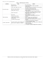
Page 50: ...harge or undercharge Recover refrigerant evacuate system and recharge to capacities shown on rating plate Defective compressor Replace and determine cause Insufficient line voltage Determine cause and...

Page 51: ...r air Purge as necessary NOTE After purging gas line of air wait at least 5 minutes for any gas to dissipate before attempting to light unit 2 Check gas valve Inadequate heating Dirty air filter Clean...

Page 52: ...ame sense fault LED 3 flashes The IGC sensed flame that should not be present Reset unit If problem persists replace control board 4 consecutive limit switch faults LED 4 flashes Inadequate airflow to...

Page 53: ...Y THAT UNIT INSTALLATION IS LEVEL CHECK FAN WHEEL AND PROPELLER FOR LOCATION IN HOUSING ORIFICE AND SETSCREW TIGHTNESS III START UP ELECTRICAL SUPPLY VOLTAGE_______________________________________ COM...

Page 54: ...eet Indianapolis IN 46231 Catalog No II577C 17 Edition Date 01 20 Replaces II577C 16 577C C 577C E 577C F Installation Instructions Manufacturer reserves the right to change at any time specifications...

Reviews: