

9
Be sure to unplug and inspect the unit before proceeding with these steps. Start with problem 1, then problem 2 and so on.
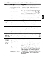
Table 6 – Troubleshooting
Problem:
Possible causes:
You should try this:
1. Unit does not
work.
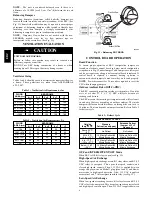
S
Erratic operation of the electronic
circuit.
S
Unplug the unit. Wait for 30 seconds. Plug it back in.
S
The breaker in the electrical panel
may be tripped.
S
Reset breaker. If it trips again, unplug the unit and call an electrician.
S
The door switch may be defective
S
Using a multimeter, check for power across the switch (the door switch
must be pushed in for this test). If there is no power, replace the switch.
S
The circuit board may be
defective.
S
Jump “B” and “G” (BLACK and GREEN). If unit
switches to high speed, remove the wall control
and test it right beside the unit using another
shorter wire. If the wall control works there, change
the wire. If it does not, change the wall control.
S
The fan motor may be defective.
S
Unplug the unit and disconnect the fan motor (4 wires). Supply 120 V
directly to the GREY and ORANGE wires of the fan motor. Replace the
motor if not working.
S
The 9--pin connector may have a
loose connection.
S
Unplug the unit and check to make sure all the crimp connections are
sound. Check the fan motor and the damper actuator connections as well.
2. The damper
actuator does not
work.
S
The 9--pin connector may have a
loose connection.
S
Unplug the unit and check to make sure all the crimp connections are
secured. Check the damper actuator connections as well.
S
The damper actuator may be
defective.
S
Feed 120 V directly to the damper actuator. If the problem persists,
replace the damper actuator.
S
The circuit board may be
defective.
S
Replace the circuit board if the problem is not solved by the above.
3. The wall control
will not work.
S
The wire in the wall OR the wall
control may be defective.
S
Remove the wall control and test it right beside the unit using another
shorter wire. If the wall control works there, change the wire. If it does
not, change the wall control.
S
The wires may be in reverse
position.
S
Ensure that the color coded wires have been connected to their
appropriate places.
S
The wires may be broken.
S
Inspect every wire and replace any that are damaged.
S
There may be a short--circuit.
S
With the help of a multimeter, check for continuity.
4. The 20--minute
lighted push--
button switch
doesn’t work OR
its indicator light
doesn’t stay on.
S
The switch may be defective.
S
The wires may be defective OR
may not be connected properly.
S
Jump the OL and OC terminals. If the unit switches to high
speed, then the wires are not the problem. Replace the
push--button.
S
Ensure that the color--coded wires have been connected to
their appropriate places.
5. The defrost cycle
does not work
(the fresh air
duct is frozen
OR the fresh air
distributed is
very cold.)
S
Ice deposits may be hindering the
damper operation.
S
Remove the ice.
S
The damper rod or the port damper
itself may be broken.
S
Inspect these parts and replace if necessary.
S
The damper actuator may be
defective.
S
Plug in the unit and select “OFF”. Press the door switch and see if the
port damper closes. If it does not close, feed 120V directly to the damper
actuator. If the port damper still does not close, replace the damper
actuator.
S
The circuit board may be
defective.
S
Unplug the unit. Unplug the defrost sensor wire (see J4 on electrical
diagram). Plug the unit back in. Select “MIN” and make sure the unit is
adjusted for low speed operation. Wait 3 minutes. The unit should switch
to high speed and the damper at the fresh air intake port should close
(defrost mode). If this does not happen, then replace the circuit board.
S
The thermistor may be defective.
S
If the defrost mode works well after having disconnected the thermistor
wire (above test), this means the thermistor is probably defective. It
should be replaced.
ER
V