

2
A07572
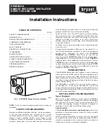
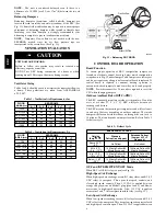
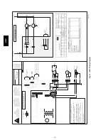
Fig. 2 -- ERV Airflow During Air Exchange
5
7
6
9
10
3
4
8
1
2
A07613
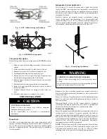
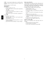
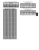
Fig. 3 -- ERVBBHA Components
Component Description
The following listed items are components of ERVBBHA (see Fig.
3).
1. Stale air return from building connected to return--air duct
system.
2. Fresh--air intake connected to outdoor air inlet hood.
3. Exhaust--air connected to outdoor air exhaust hood.
4. Mechanical filters trap dust contained in the air.
5. Energy recovery core is a cross--flow type. It transfers sensi-
ble and latent energy between the 2 air streams.
6. Blowers bring in fresh--air from outside and exhaust stale--
air to outside.
7. Electronic control circuit ensures proper unit operation.
8. Fresh--air supply from ERV connected to return--air duct of
forced air system.
9. Terminal connector block for wiring wall and timer con-
trols.
10. Electrical cord connects to standard 115v outlet.
UNIT INSTALLATION
UNIT DAMAGE HAZARD
Failure to follow this caution may result in equipment
damage or improper operation.
Do not install ERV in a corrosive or contaminated
atmosphere.
CAUTION
!
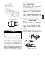
Mount Unit
The ERV can be suspended from floor joists using chains and 4
springs. Attach metal hanging bracket to all 4 sides of cabinet (see
Fig. 4). The unit may be installed on a shelf if an isolation pad is
provided to dampen vibration. Unit should always be installed as
level as possible.
Independent System Application
In the absence of a forced--air system and a typical duct system
layout, the ERV can be applied as an independent or stand alone
unit. To ensure comfort, this type of application involves running
both fresh--air and return--air registers (or stale--air pickup registers)
throughout the home.
Fresh--air registers are normally located in bedrooms, dining
rooms, living rooms, and basements. It is recommended that
registers be placed 6 to 12” (152 to 305 mm) from the ceiling on an
interior wall and airflow directed toward the ceiling. If registers are
floor installed, airflow should be directed toward the wall.
A92269
Fig. 4 -- Chain Spring Installation
CARBON MONOXIDE POISONING HAZARD
Failure to follow this warning could result in personal injury
or death.
Do not install return--air registers (or stale--air pickup registers)
in same room as gas furnace or water heater.
!
WARNING
Return--air (or stale--air pickup registers) are normally located to
draw from kitchens, bathrooms, basements, or other rooms where
stale--air can exist.
Proper size and type of registers must be used to minimize pressure
drop. The velocity of airflow through register should not be above
400 ft per minute.
Maximum length of duct for the system should be designed
according to the highest speed of the unit. Refer to specifications
listed in unit Product Data Digest for ventilation capacities.
Forced--Air Application
Most ERV applications will be installed in conjunction with new or
existing forced--air systems. To operate properly, the fresh--air
supply and stale--air return from ERV connect directly to return--air
duct system. This is how the ERV distributes fresh air and removes
stale air from inside of building (see Fig. 5). For these installations,
furnace or fan coil blower must be interlocked and operate
continuously whenever ERV is energized.
NOTE
: The fresh air from ERV is introduced into return--air duct
at a point no less than 6 ft (1.8 m) upstream of furnace or fan coil.
This connection should be direct (see Fig. 5). This is to allow
incoming fresh--air to mix before entering indoor equipment.
ER
V