background image

18

11

NO PREVIOUS CODE – Stored codes

are 

erased 

after 72 hours

.  On RED LED

boards stored status codes can also b

e

erased whene

v

er po

wer (115V or 24V

)

is interr

upted.

  Run system through

 a

heating or cooling cycle to

 chec

k system.

12

BLO

WER ON AFTER PO

WER UP 

(115V OR 24V) – Nor

mal operation.

Bl

ow

er r

uns f

or 90 seconds

, if unit is

po

wered up during a call f

or heat (R-W

closed) or when (R-W o

pens) dur

ing 

th

e

b

lo

w

er on-dela

y per

iod.

1

3

LIMIT CIR

CUIT LOCK

O

UT – Loc

kout

occurs if the limit or flame rollout s

w

itch is

open l

onger t

han 3 minutes

.  Control wil

l

auto-r

eset after 3 hours

.  

See code 33

.

1

4

IGNITION 

LOCK

OUT – System f

ailed to

ignite gas 

and pro

v

e

 flame in 4 

attempts

.

Control will auto-reset after 3 hours

.

See status code 34.

21

GAS HEA

TING LOCK

OUT – 

T

u

rn off

po

wer and w

ait 5 minutes to retr

y.

Chec

k f

o

r:

-

S

tuc

k closed g

as v

a

lv

e rela

y

 on cont

rol.

-

M

is

wire or shor

t to gas v

alv

e wire

.

2

2

ABNORM

AL FLAME-PR

O

VING 

SIGNAL

Flame is pro

v

ed while gas v

alv

e is de-

energiz

ed.

  Inducer will r

un until f

ault is

cleared.

  Chec

k f

o

r:

-

S

tuc

k open or leaky gas v

a

lv

e

.

23

PRESSURE SWITCH DID NO

T OPEN

Chec

k f

o

r:

-

O

bstr

ucted pressure

 tube

.

-

P

ressure s

witch stuc

k closed.

24

SECOND

AR

Y

 V

O

LT

A

G

FUSE 

IS 

OPEN

Chec

k f

o

r:

-S

h

o

rt circuit in secondar

vo

ltage (24V)

wir

ing including ther

mostat leads

.

D

isconnect ther

mostat leads to isolate

shor

t circuit.

3

1

PRESSURE 

SWITCH DID NO

T CLOSE

OR REOPENED – If open longer than 

5

minute

s

, inducer shuts off f

or 15 minutes

bef

ore retr

y.

  If opens dur

ing b

lo

w

er on-

dela

per

iod, 

b

lo

w

er will come on 

for th

e

selected b

lo

w

er off-dela

y.

  Chec

k f

o

r:

-

P

roper v

ent sizing.

-

L

o

w

 inducer v

oltage (115V).

-

L

o

w

 inlet 

gas pressure

 (if LGPS used).

-

Inadequate comb

ustion air supply

.

-D

isconnected or obs

tr

ucted pressure

tubing.

-D

ef

ectiv

e inducer motor

.

-D

ef

ectiv

e pressure s

witch.

-

E

xcessiv

e wind.

-R

estr

icted v

ent.

33

LIMIT CIRCUIT F

AU

LT

 – Indicates the

limit or flame 

rollout s

witch 

is 

open.

 Blo

w

er

will r

un f

or 4 minutes 

or until open 

sw

itc

h

remak

es whiche

v

er is longer

.  If open

longer than 3 minut

e

s

, code changes to

loc

k

out #13.

  If open less than

 3 min.

status code #33 continues to flash un

til

b

lo

w

er shuts off

.  Flame rollout s

witch

requires manual reset.

  Chec

k f

o

r:

-

D

ir

ty filter or restr

icted duct system

.

-

Loose b

lo

w

er wheel.

-

D

ef

ectiv

e s

witch or conn

ections

.

-D

ef

ectiv

e b

lo

w

er motor or capacitor

.

-

Inadequate comb

ustion air su

pply

(flame rollout s

witch open).

-R

estr

icted v

ent.

-

P

roper v

ent sizing.

-

E

xcessiv

e wind.

-  Blo

w

er motor on incorrect speed tap

.

-  Input rate to fur

nace set too high.

34

IGNITI

ON PR

O

V

ING 

F

AILURE 

– If 

flame

is not sensed dur

ing the tr

ial f

or ignition

per

iod, 

the control will repe

at the ignition

sequence 3 more times bef

ore lo

ck

out

#14 occur

s

.  If flame signal is lost dur

ing

the b

lo

w

er on-dela

y per

iod, b

lo

w

er wil

l

come on f

o

r the selected 

b

lo

w

er off-dela

y.

 Chec

k the f

ollo

w

ing items first bef

ore

proceeding to

 the ne

xt step

.

-

G

as v

alv

e tur

ned off

.

-

M

anual shut-off v

alv

e

.

-G

reen/Y

ello

w

 wire 

MUST be connected

to fur

nace sheet metal

.

-

F

lame sensor m

ust not be grounded.

T

o

 deter

mine whether the prob

lem is in

the gas v

a

lv

e

igniter

, or flame sensor the

system can be operated 

in the component

test mode to chec

k the ignit

er

.  First

remo

ve

 the R ther

mostat connection from

the control and initiate the component

test sequence

.  Does the igniter gl

ow

orange/white 

b

y

 the end of the 15 second

w

a

rm

-up per

iod?

Unplug igniter har

ness 

from control and initiate

another component 

test sequence

.  Chec

k

for 115V between 

pin 1 and 

NEUTRAL-L2 

on

the control.


W

as 115V present f

or the 15

second per

iod?

Reconnect the R the

rm

ostat lead and set

ther

mostat to call f

o

r heat.

  Connect

 v

o

ltmeter

across gas v

a

lv

e

 connections

.  Does gas v

a

lv

e

receiv

e 24V?

Does gas v

alv

e open and allo

w

 gas to flo

w

?

Do the main b

ur

ners ignite?

Do the main b

ur

ners sta

y on?

Repeat call f

or heat and chec

k flame sensor

current dur

ing tr

ial f

or ignition per

iod.

  Is the

DC microamps bel

ow

 0.5?

Is current near typical v

alue?

Will main b

ur

ners ignite and sta

y on?

Fix

ed.

Clean flame 

sensor with fine steel wool and

rechec

k current.

  Nominal current i

s 4.0 to 6.0

microamps

.

45

CONTR

O

L CIRCUITR

Y LOCK

OUT

A

uto-reset after 1 hour lo

c

k

out due to:

-

F

lame circuit f

ailure

.

-

G

as v

alv

e rela

y stuc

k open.

-

S

oftw

are chec

k error

.

Reset po

wer to clear lo

c

k

out.

  Replace

control if code re

peats

.

Replace fur

nace control

.

Chec

fo

continuity in the 

har

n

ess 

and 

ignit

er

.

 Replace def

ectiv

e component.

Chec

k connections

.  If OK, replace control

.

Chec

k that all gas v

alv

es are tur

ned on.

Replace v

al

ve

.

Chec

k f

o

r:

-

Inadequate flame carr

yov

er or rough

ignition.

-

L

o

w

 inlet gas pressure

.

-

P

roper fir

ing rate

.

Allo

w

 b

lo

w

er to come on and repeat test to

chec

k f

or inter

mittent operation.

Chec

k connections and retr

y.

  If current is

near typical 

v

alue (4.0-6.0

 nominal) and

b

u

rners will not sta

y on, replace

 control.

Replace electrode

.

Replace fur

nace control

.

YES

YES

YES

YES

NO

YES

YES

YES

NO

YES

NO

NO

NO

YES

NO

NO

NO

NO

A05096

340AA

V

Summary of Contents for Deluxe 340AAV

Page 1: ...potential for personal injury Understand the signal words DANGER WARNING and CAUTION These words are used with the safety alert symbol DANGER identifies the most serious hazards which will result in severe personal injury or death WARNING signifies a hazard which could result in personal injury or death CAUTION is used to identify unsafe practices which may result in minor personal injury or produ...

Page 2: ... operation CAUTION GENERAL This furnace can be installed as a direct vent 2 pipe or non direct vent 1 pipe condensing gas furnace These instructions are written as if the furnace is installed in an upflow application An upflow furnace application is where the blower is located below the combustion and controls section of the furnace and conditioned air is discharged upward Since this furnace can b...

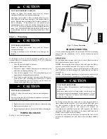
Page 3: ...the label attached to the furnace WARNING The minimum maintenance that should be performed on this equipment is as follows 1 Check and clean or replace air filter each month as needed 2 Check blower motor and wheel for cleanliness annually 3 Check electrical connections for tightness and controls for proper operation each heating season Service as necessary 4 Check for proper condensate drainage C...

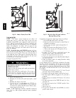
Page 4: ...nfiguration Shown with Blower Access Panel Removed 1 Turn off electrical supply to furnace 2 Remove filter cabinet door 3 Slide filter out of cabinet 4 If equipped with permanent washable filter clean filter by spraying cold tap water through filter in opposite direction of airflow Rinse filter and let dry Oiling or coating of the filter is not recommended 5 If equipped with factory specified disp...

Page 5: ... CAUTION g Clean wheel per instructions on degreaser cleaner Do not get degreaser in motor 9 Reassemble motor and blower wheel by reversing items 8b through 8f Ensure wheel is positioned for proper rotation Be sure to reattach ground wire Tighten setscrew to 140 to 160 in lb torque NOTE Be sure to attach ground wire to blower housing 10 Reinstall blower assembly in furnace 11 Reinstall control box...

Page 6: ...move screws attaching burner assembly in burner box NOTE Use care when removing and reinstalling burners not to strike the hot surface igniter IGNITER WIRES MUST BE PLACED IN THIS SLOT A05074 Fig 7 Igniter Wire Placement 12 Remove burner assembly from burner box NOTE All burners are attached to burner bracket and can be removed as one assembly 13 Clean burners with soft brush and vacuum 14 Reinsta...

Page 7: ...sconnect wires or connectors to flame rollout switch gas valve igniter and flame sensor 4 Disconnect combustion air intake pipe from intake hous ing 5 Remove the pressure switch tube from intake housing 6 Remove screws attaching intake housing to burner box and rotate intake housing away from burner box for removal 7 Using backup wrench disconnect gas supply pipe from fur nace gas control valve 8 ...

Page 8: ...n made specifically for the detection of leaks to check all connections WARNING 18 Replace main furnace door Secondary Heat Exchangers NOTE The condensing side inside of the secondary heat exchangers CANNOT be serviced or inspected A small number of bottom outlet openings can be inspected by removing the inducer assembly See Flushing Collector Box and Drainage System section for details on removin...

Page 9: ...onnection as shown 3 HORIZONTAL LEFT installations require the collector box pressure tube to be relocated between the inducer housing and the blower shelf to prevent a trap Refer to the Installation Instructions for further details NOTE 324999 201 REV C FIELD INSTALLED FACTORY SUPPLIED DRAINTUBE COUPLING RIGHT DRAIN OPTION BURNER ENCLOSURE PRESSURE REFERENCE TUBE ASSEMBLY BURNER ENCLOSURE PRESSUR...

Page 10: ...triking the igniter on surrounding parts Note that the igniter bracket has a handle that extends to the front of the burner box to aid in handling See Fig 13 d Inspect igniter for signs of damage or failure UNIT DAMAGE HAZARD Failure to follow this caution may result in premature failure of the igniter The igniter is fragile DO NOT allow it to hit burner box parts while removing or replacing it CA...

Page 11: ...se to blow If fuse replacement is required use ONLY a fuse of identical size The furnace control LED will flash status code 24 when fuse needs to be replaced With power to the unit disconnected check all electrical connections for tightness Tighten all screws on electrical connections If any smoky or burned connections are found disassemble the connection clean all parts strip wire and reassemble ...

Page 12: ... same type or equivalent wire W Y GND THERMOSTAT TERMINALS 1 2 3 A02174 Fig 15 Field Wiring BLW NUETRAL STATUS CODE LED SEC 2 SEC 1 EAC 2 L2 FUSE 3 AMP 0 5 AMP 24VAC HUM TEST TWIN G Com W Y R 24V 120 180 90 150 BLOWER OFF DELAY PLT 1 COOL HEAT SPARE 1 SPARE 2 EAC 1 1 AMP 115VAC PR 1 L1 PL2 1 24 V THERMOSTAT TERMINALS 3 AMP FUSE LED OPERATION DIAGNOSTIC LIGHT 115 VAC L2 NEUTRAL CONNECTIONS COOL HEA...

Page 13: ...omotive type CAUTION 6 Replace drain connection cap and clamp to inducer housing 7 Replace main furnace door 8 Propylene glycol need not be removed before restarting fur nace WIRING DIAGRAMS See Fig 21 for wiring diagram A07911 Fig 17 Freeze Protection TROUBLESHOOTING Use the troubleshooting guide the status code LED on the furnace control and the component test to isolate furnace operation proble...

Page 14: ... COM 24v terminals are jumpered longer than 2 sec LED will flash rapidly and ignore component test request A99119 Fig 19 Funnel in Drain Tube and Antifreeze Running Through Trap Component test sequence for single stage furnace is as follows a LED will display status code 11 four times b Inducer motor starts and continues to run until Step f of component test sequence c After 7 sec the hot surface ...

Page 15: ...T CLOSE OR REOPENED If open longer than five minutes inducer shuts off for 15 minutes before retry Check for Excessive wind Proper vent sizing Defective inducer motor Low inducer voltage 115VAC Defective pressure switch Inadequate combustion air supply Restricted vent Disconnected or obstructed pressure tubing Low inlet gas pressure if LGPS used If it opens during blower on delay period blower wil...

Page 16: ...AFT MOTOR RELAY SPST N O ILK BLOWER ACCESS PANEL INTERLOCK SWITCH SPST N O J1 BLOWER OFF DELAY JUMPER SELECTOR J2 COOLING OFF DELAY JUMPER JB JUNCTION BOX LED LIGHT EMITTING DIODE FOR STATUS CODES RED LGPS LOW GAS PRESSURE SWITCH SPST N O LS LIMIT SWITCH AUTO RESET SPST N C OL AUTO RESET INTERNAL MOTOR OVERLOAD TEMPERATURE SWITCH N C PCB PRINTED CIRCUIT BOARD CONTROL PL1 11 CIRCUIT PCB CONNECTOR P...

Page 17: ...est sequence The inducer will start and run for the entire component test The HSI blower motor FAN speed AMBER LED boards only HEAT speed and COOL speed will run for 10 15 seconds each Gas valve and humidifier will not be turned on Was there a previous status code other than 11 Is door switch closed Is there 115V going to switch Replace door switch Replace transformer Does the control respond to W...

Page 18: ... switch open Restricted vent Proper vent sizing Excessive wind Blower motor on incorrect speed tap Input rate to furnace set too high 34 IGNITION PROVING FAILURE If flame is not sensed during the trial for ignition period the control will repeat the ignition sequence 3 more times before lockout 14 occurs If flame signal is lost during the blower on delay period blower will come on for the selected...

Page 19: ...heory and skills programs is available using popular video based formats and materials All include video and or slides plus companion book Classroom ServiceTraining plus hands on the products in our labs can mean increased confidence that really pays dividends in faster troubleshooting fewer callbacks Course descriptions and schedules are in our catalog CALL FOR FREE CATALOG 1 800 644 5544 Package...

Page 20: ...hange at any time specifications or designs without notice and without incurring obligations E2008 Bryant Heating Cooling Systems D 7310 W Morris St D Indianapolis IN 46231 Printed in U S A Edition Date 12 08 Replaces SP05 72 Catalog No SM340AAV 01 340AAV ...

Reviews: