background image

44

General

The sequence below describes the sequence of operation for an

electromechanical unit with and without a factory installed
EconoMi$er IV and X (called “economizer” in this sequence).

For information regarding a direct digital controller, see the

start-up, operations, and troubleshooting manual for the appli-
cable controller.

Electromechanical units with no economizer
Cooling (Single speed indoor fan motor)

When the thermostat calls for cooling, terminals G and Y1 are
energized. As a result, the indoor fan contactor (IFC) and the

compressor contactor (C1) are energized, causing the indoor

fan motor (IFM), compressor #1, and outdoor fan to start. If the
unit has 2 stages of cooling, the thermostat will additionally

energize Y2. The Y2 signal will energize compressor contactor

#2 (C2), causing compressor #2 to start. Regardless of the num-
ber of stages, the outdoor fan motor runs continuously while

unit is cooling. When SAV system is utilized, indoor fan motor

runs at design CFM (full speed) during the heating operation.

Heating (Single speed indoor fan motor)

When the thermostat calls for heating, power is sent to W on

the Integrated Gas Controller (IGC) board. An LED (light-

emitting diode) on the IGC board turns on and remains on
during normal operation. A check is made to ensure that the

rollout switch and limit switch are closed. If the check was suc-

cessful, the induced-draft motor is energized, and when its
speed is satisfactory, as proven by the “hall effect” sensor, the

ignition activation period begins. The burners will ignite within

5 seconds. If the burners do not light, there is a 22-second delay
before another 5-second attempt. This sequence is repeated for

15 minutes or until the burners light. If, after the 15 minutes,

the burners still have not lit, heating is locked out. To reset the
control, break 24-v power to the thermostat.
When ignition occurs, the IGC board will continue to monitor

the condition of the rollout switch, the limit switches, the “hall
effect” sensor, as well as the flame sensor. 45 seconds after

ignition occurs, assuming the unit is controlled through a room

thermostat set for fan auto, the indoor fan motor will energize
(and the outdoor air dampers will open to their minimum posi-

tion). If, for some reason, the over-temperature limit opens

prior to the start of the indoor fan blower, the unit will shorten
the 45-second delay to 5 seconds less than the time from initia-

tion of heat to when the limit tripped. Gas will not be inter-

rupted to the burners and heating will continue. Once the fan-
on delay has been modified, it will not change back to 45 sec-

onds until power is reset to the control.
On units with 2 stages of heat, when additional heat is required,
W2 closes and initiates power to the second stage of the main

gas valve. When the thermostat is satisfied, W1 and W2 open

and the gas valve closes, interrupting the flow of gas to the
main burners.
If the call for W1 lasted less than 1 minute, the heating cycle will
not terminate until 1 minute after W1 became active. If the unit is

controlled through a room thermostat set for fan auto, the indoor

fan motor will continue to operate for an additional 45 seconds
then stop. If the over-temperature limit opens after the indoor

motor is stopped, but within 10 minutes of W1 becoming inac-

tive, on the next cycle the time will be extended by 15 seconds.
The maximum delay is 3 minutes. Once modified, the fan off

delay will not change back to 45 seconds unless power is reset to

the control. A LED indicator is provided on the IGC to monitor
operation.

Electromechanical units with an economizer
Cooling

When free cooling is not available, the compressors will be

controlled by the zone thermostat. When free cooling is avail-
able, the outdoor air damper is modulated by the EconoMi$er

IV and X control to provide a 50°F (10°C) to 55°F (13°C)
mixed air temperature into the zone. As the mixed air tempera-

ture fluctuates above 55°F (13°C) or below 50°F (10°C) damp-

ers will be modulated (open or close) to bring the mixed air
temperature back within control. If mechanical cooling is uti-

lized with free cooling, the outdoor air damper will maintain its

current position at the time the compressor is started. If the
increase in cooling capacity causes the mixed air temperature

to drop below 45°F (7°C), then the outdoor air damper position

will be decreased to the minimum position. If the mixed air
temperature continues to fall, the outdoor air damper will close.

Control returns to normal once the mixed air temperature rises

above 48°F (9°C). The power exhaust fans will be energized
and de-energized, if installed, as the outdoor air damper opens

and closes.
If field-installed accessory CO

2

 sensors are connected to the

EconoMi$er IV and X control, a demand controlled ventilation

strategy will begin to operate. As the CO

level in the zone

increases above the CO

2

 setpoint, the minimum position of the

damper will be increased proportionally. As the CO

2

 level

decreases because of the increase in fresh air, the outdoor air

damper will be proportionally closed. For EconoMi$er IV and
X operation, there must be a thermostat call for the fan (G).
If the unit is occupied and the fan is on, the damper will operate

at minimum position. Otherwise, the damper will be closed.
If field-installed accessory CO

2

 sensors are connected to the

EconoMi$er IV and X control, a demand controlled ventilation

strategy will begin to operate. As the CO

level in the zone

increases above the CO

2

 setpoint, the minimum position of the

damper will be increased proportionally. As the CO

2

 level

decreases because of the increase in fresh air, the outdoor air
damper will be proportionally closed. For EconoMi$er IV and

X operation, there must be a thermostat call for the fan (G). If

the unit is occupied and the fan is on, the damper will operate at
minimum position. Otherwise, the damper will be closed.
When the EconoMi$er IV and X control is in the occupied

mode and a call for cooling exists (Y1 on the thermostat), the
control will first check for indoor fan operation. If the fan is not

on, then cooling will not be activated. If the fan is on, then the

control will open the EconoMi$er IV and X damper to the min-
imum position. 
On the initial power to the EconoMi$er IV and X control, it

will take the damper up to 2

1

/

2

 minutes before it begins to posi-

tion itself. After the initial power-up, further changes in damper

position can take up to 30 seconds to initiate. Damper move-
ment from full closed to full open (or vice versa) will take

between 1

1

/

2

 and 2

1

/

2

 minutes. If free cooling can be used as

determined from the appropriate changeover command
(switch, dry bulb, enthalpy curve, differential dry bulb, or dif-

ferential enthalpy), then the control will modulate the dampers

open to maintain the mixed air temperature setpoint at 50°F
(10°C) to 55°F (13°C). If there is a further demand for cooling

SEQUENCE OF OPERATION

Summary of Contents for 582J Series

Page 1: ...Copyright 2019 Bryant Corporation Form PDS582J 4 6 06 Product Data 582J LEGACY LINE SINGLE PACKAGED ROOFTOP 14 SEER GAS HEAT ELECTRIC COOLING 3 to 5 NOMINAL TONS ...

Page 2: ...o our large control box gives you room to work and room to mount Bryant accessory controls Easy to maintain Easy access handles by Bryant provide quick and easy access to all normally serviced components Our no strip screw system has superior holding power and guides screws into position while preventing the screw from stripping the unit s metal Take accurate pressure readings by reading condenser...

Page 3: ...ted wiring and power wiring drawings are affixed to unit making troubleshooting easy Single central terminal board for test and wiring connections Fast access handled panels for easy access on normally accessed service panels No strip screw system guides screws into the panel and captures them tightly without stripping the screw the panel or the unit Mechanical cooling 115 F to 40 F or 46 C to 4 C...

Page 4: ... Guard P E coat Al Cu Al Cu Louvered Hail Guard Q E coat Al Cu E coat Al Cu Louvered Hail Guard R Cu Cu Al Cu Louvered Hail Guard S Cu Cu Cu Cu Louvered Hail Guard Voltage E 460 3 60 J 208 230 1 60 P 208 230 3 60 T 575 3 60 Outdoor Air Options A None B Temperature Economizer Barometric Relief Standard Leak W7212 or W7220 E Temperature Economizer Barometric Relief Standard Leak w CO2 W7212 or W7220...

Page 5: ...vel AHRI COOLING RATING TABLE UNIT COOLING STAGES NOM CAPACITY TONS NET COOLING CAPACITY MHBH TOTAL POWER kW SEER EER 582J 04 1 3 35 4 3 0 14 0 12 00 582J 05 1 4 47 5 4 0 14 0 12 00 582J 06 1 5 58 5 4 9 14 1 12 00 AHRI Air Conditioning Heating and Refrigeration Institute Test Standard ASHRAE American Society of Heating Refrigerating and Air Condition ing Engineers EER Energy Efficiency Ratio SEER ...

Page 6: ...2 0 81 3 MED 90 73 5 30 60 82 0 81 5 HIGH 05 LOW 60 49 20 50 82 0 81 3 MED 90 73 5 30 60 82 0 81 5 HIGH 120 98 40 70 82 0 81 3 06 LOW 60 49 15 50 82 0 81 3 MED 90 73 5 25 60 82 0 81 5 HIGH 120 98 35 70 82 0 81 3 SOUND PERFORMANCE TABLE 582J UNIT COOLING STAGES OUTDOOR SOUND dB AT 60 Hz A WEIGHTED 63 125 250 500 1000 2000 4000 8000 04 A 1 76 78 2 78 0 74 2 73 3 70 6 66 0 62 4 56 9 05 A 1 81 90 9 84...

Page 7: ...8 48 Fan Qty Type 1 Centrifugal 1 Centrifugal 1 Centrifugal Fan Diameter in 10 x 10 10 x 10 10 x 10 MEDIUM STATIC 1 PHASE Motor Qty Drive Type 1 Belt 1 Belt 1 Belt Max BHP 1 2 1 2 1 5 RPM Range 770 1175 770 1175 1035 1466 Motor Frame Size 48 48 56 Fan Qty Type 1 Centrifugal 1 Centrifugal 1 Centrifugal Fan Diameter in 10 x 10 10 x 10 10 x 10 HIGH STATIC 1 PHASE Motor Qty Drive Type 1 Belt 1 Belt N ...

Page 8: ... 8 in RTPF 3 8 in RTPF Rows FPI 1 17 2 17 2 17 Total Face Area ft2 16 5 14 6 18 8 COND FAN MOTOR Qty Motor Drive Type 1 Direct 1 Direct 1 Direct Motor HP RPM 1 8 825 1 4 1100 1 4 1100 Fan diameter in 22 22 22 FILTERS RA Filter Size in 2 16 x 25 x 2 2 16 x 25 x 2 4 16 x 16 x 2 OA inlet screen Size in 1 20 x 24 x 1 1 20 x 24 x 1 1 20 x 24 x 1 PHYSICAL DATA COOLING 3 5 TONS cont 582J 04A B 582J 05A B...

Page 9: ...ens closes F 195 115 195 115 Temperature rise F 45 80 35 80 LIQUID PROPANE HEAT LOW of stages of burners total 1 2 1 2 1 2 Connection size 1 2 in NPT 1 2 in NPT 1 2 in NPT Rollout switch opens closes F 195 115 195 115 195 115 Temperature rise F 25 55 20 55 15 55 MED of stages of burners total 1 or 2 3 1 3 1 3 Connection Size 1 2 in NPT 1 2 in NPT 1 2 in NPT Rollout switch opens closes F 195 115 19...

Page 10: ...F 195 115 195 115 Temperature rise F 50 80 40 80 LIQUID PROPANE HEAT LOW of stages of burners total 1 2 1 2 1 2 Connection size 1 2 in NPT 1 2 in NPT 1 2 in NPT Rollout switch opens closes F 195 115 195 115 195 115 Temperature rise F 25 55 25 55 20 55 MED of stages of burners total 1 or 2 3 1 3 1 3 Connection size 1 2 in NPT 1 2 in NPT 1 2 in NPT Rollout switch opens closes F 195 115 195 115 195 1...

Page 11: ...mpressor delay control circuit X Phase Monitor X ECONOMIZERS AND OUTDOOR AIR DAMPERS EconoMi er IV for electro mechnical controls Non FDD Standard air leak damper models 5 6 X X EconoMi er2 for DDC controls complies with FDD Standard and Ultra Low Leak air damper models 5 7 X X Motorized 2 position outdoor air damper5 X X Manual outdoor air damper 25 and 50 X Barometric relief1 X X Power exhaust X...

Page 12: ... needing com plicated translators or adapter modules using the RTU Open controller This new controller speaks the 4 most common building automation system languages BACnet1 Modbus2 N2 and LonWorks3 Use this controller when you have an existing BAS Time Guard II control circuit This accessory protects your compressor by preventing short cycling in the event of some other failure and prevents the co...

Page 13: ...ger option provides the tubular heat exchanger made out of a minimum 20 gage type 409 stain less steel for applications where the mixed air to the heat exchanger is expected to drop below 45 F 7 C Stainless steel may be specified on applications where the presence of air borne contaminants require its use applications such as paper mills or in areas with very high outdoor humidity that may result ...

Page 14: ...Medium gas heat 12 5 9 4 9 4 High gas heat 17 8 17 8 Hail guard louvered 13 6 13 6 17 8 Cu Cu Condenser Coil2 37 17 74 34 95 43 Cu Cu Condenser and Evaporator Coils2 75 34 112 51 165 75 Roof curb 14 in curb 115 52 115 52 115 52 Roof curb 24 in curb 197 89 197 89 197 89 CO2 sensor 2 1 2 1 2 1 Flue discharge deflector 7 3 7 3 7 3 Optional indoor motor drive 6 3 6 3 17 8 Motormaster controller 9 4 9 ...

Page 15: ...15 582J 04 06 BASE UNIT DIMENSIONS BASE UNIT DIMENSIONS ...

Page 16: ...16 582J 04 06 CORNER WEIGHTS BASE UNIT DIMENSIONS CONT ...

Page 17: ...vicer is grounded e g metal masonry wall 36 in 914 mm Surface behind servicer is electrically non conductive e g wood fiberglass Special Check sources of flue products within 10 ft 3 m of unit fresh air intake hood C 36 in 914 mm Side condensate drain is used 18 in 457 mm Minimum clearance D 48 in 1219 mm No flue discharge accessory installed surface is combustible material 42 in 1067 mm Surface b...

Page 18: ... 1 DEC 2 DEC 3 DEC ANG MATERIAL AUTHORIZATION NUMBER TITLE 1041738 CURB ASY ROOF ENGINEERING MANUFACTURING 004 007 ENGINEERING REQUIREMENTS SIZE DRAWING NUMBER REV T 005 Y 002 DRAFTER CHECKER D 48TC400427 B WEIGHT MMC 06 17 11 SHEET 5 OF 5 SURFACE FINISH MFG PURCH MODEL INTERNAL USE ONLY NEXT DRAWING SCALE DISTRIBUTION PURCH N A MMC NOTES 1 ROOFCURB ACCESSORY IS SHIPPED DISASSEMBLED 2 INSULATED PA...

Page 19: ...plications Also consider the various economizer control methods and their benefits as well as sensors required to accomplish your application goals Please contact your local Bryant representative for assistance Motor limits Brake horsepower BHP Due to internal design of Bryant units the air path and specially designed motors the full horsepower maximum continuous BHP band as listed in PHYSICAL DAT...

Page 20: ...ss the outdoor air is excessively humid or contaminated economizer based free cooling is the preferred less costly and energy conscious method In low ambient applications where outside air might not be desired such as contaminated or excessively humid outdoor environments your Bryant rooftop can operate at ambient temperatures down to 20 F 29 C using the recommended accessory Motormaster low ambie...

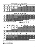
Page 21: ...6 24 1 28 6 16 9 20 8 24 8 67 TC 38 8 38 8 38 8 36 4 36 4 36 4 33 3 33 3 33 3 27 7 27 7 29 2 21 6 21 6 26 5 SHC 21 9 27 7 33 5 20 9 26 7 32 6 19 6 25 5 31 4 17 4 23 3 29 2 15 0 20 8 26 5 72 TC 42 4 42 4 42 4 40 1 40 1 40 1 37 7 37 7 37 7 34 5 34 5 34 5 30 9 30 9 30 9 SHC 15 8 21 6 27 4 14 9 20 7 26 5 13 9 19 8 25 6 12 7 18 7 24 6 11 4 17 4 23 3 76 TC 44 9 44 9 42 7 42 7 40 3 40 3 37 7 3 7 34 4 34 ...

Page 22: ... 31 9 30 7 33 5 34 3 34 8 31 8 27 6 SHC 15 3 20 0 26 3 25 1 20 4 15 4 14 0 18 2 21 9 kW 2 53 2 49 2 41 2 82 2 74 2 68 3 09 3 01 2 88 105 TC 32 8 28 4 23 4 18 7 23 8 29 3 24 5 18 8 13 6 SHC 11 0 14 6 17 9 13 4 10 3 7 1 2 6 5 6 8 6 kW 3 36 3 23 3 06 3 62 3 41 3 24 3 79 3 58 3 39 115 TC 31 3 32 0 31 9 30 7 33 5 34 3 34 8 31 8 27 6 SHC 15 3 20 0 26 3 25 1 20 4 15 4 14 0 18 2 21 9 kW 2 53 2 49 2 41 2 8...

Page 23: ... 18 17 18 62 18 02 18 69 18 87 SHC 5 89 7 85 9 40 4 65 6 08 7 35 3 71 5 09 5 59 kW 1 78 1 80 1 82 1 81 1 83 1 84 1 82 1 82 1 86 60 TC 17 43 18 50 18 28 18 09 19 03 19 41 18 32 18 29 19 33 SHC 7 75 10 06 9 51 7 08 8 34 9 60 6 29 6 94 7 88 kW 1 66 1 62 1 70 1 67 1 69 1 68 1 69 1 70 1 71 50 TC 17 82 18 59 19 72 18 31 19 73 20 26 18 76 20 21 20 73 SHC 6 40 7 99 10 05 4 79 6 71 7 97 3 40 5 11 6 16 kW 1...

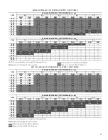
Page 24: ...1 37 8 44 4 28 4 34 5 40 7 67 TC 51 5 51 5 51 5 48 7 48 7 48 7 44 9 44 9 44 9 40 7 40 7 42 0 36 3 36 3 40 2 SHC 30 9 38 3 45 7 30 0 37 5 45 0 28 5 36 1 43 7 26 9 34 5 42 0 25 1 32 7 40 2 72 TC 55 0 55 0 55 0 52 9 52 9 52 9 50 9 50 9 50 9 47 3 47 3 47 3 43 1 43 1 43 1 SHC 20 4 27 5 34 6 19 6 26 8 33 9 18 9 26 3 33 8 17 6 25 2 32 7 16 1 23 7 31 3 76 TC 56 3 56 3 54 3 54 3 52 3 52 3 50 3 50 3 46 8 46...

Page 25: ... 34 5 34 9 35 6 42 8 40 4 37 8 42 4 43 8 39 3 SHC 16 3 20 9 27 7 36 7 23 8 16 2 16 4 26 1 34 3 kW 3 25 3 25 3 24 3 63 3 63 3 61 4 04 4 02 4 00 105 TC 44 0 40 3 33 3 26 2 33 7 41 0 34 2 26 1 18 6 SHC 15 1 22 9 28 9 22 6 17 2 11 1 5 0 10 6 15 8 kW 4 49 4 47 4 32 4 99 4 87 4 69 5 50 5 28 5 09 115 TC 33 2 33 5 38 3 39 8 37 3 35 4 40 3 42 0 41 3 SHC 15 6 20 3 31 2 34 7 22 3 15 3 15 9 26 2 39 6 kW 3 53 ...

Page 26: ... 52 SHC 7 91 10 13 11 21 6 83 8 40 9 04 5 88 7 04 7 39 kW 2 80 2 78 2 77 2 80 2 77 2 76 2 81 2 80 2 78 60 TC 27 32 28 34 21 46 27 68 16 17 25 05 28 38 18 51 20 56 SHC 13 66 15 45 13 04 11 75 4 46 12 58 11 21 10 82 10 87 kW 2 85 2 86 2 86 2 89 2 80 2 91 2 88 2 84 2 88 50 TC 11 00 11 31 12 76 14 48 13 83 13 72 15 32 15 18 17 14 SHC 7 10 9 20 11 20 5 13 6 46 9 10 4 21 4 49 6 19 kW 2 95 2 94 2 93 2 94...

Page 27: ... 62 9 41 1 50 1 59 2 37 8 46 2 54 6 67 TC 65 3 65 3 65 3 61 8 61 8 61 8 56 7 56 7 57 6 52 4 52 4 55 7 47 6 47 6 54 5 SHC 37 3 47 4 57 4 35 9 46 2 56 6 36 4 47 0 57 6 34 9 45 3 55 7 33 5 44 0 54 5 72 TC 70 2 70 2 70 2 67 0 67 0 67 0 63 2 63 2 63 2 57 3 57 3 57 3 54 0 54 0 54 0 SHC 26 1 35 4 44 8 24 5 34 1 43 7 22 8 32 7 42 6 20 6 30 1 39 5 19 6 29 5 39 3 76 TC 73 4 73 4 70 6 70 6 67 1 67 1 60 3 60 ...

Page 28: ...6 48 4 62 7 58 6 50 5 62 8 60 0 52 6 SHC 26 3 34 9 41 9 27 8 38 7 46 9 29 0 42 1 51 5 kW 4 20 4 09 3 92 3 97 4 10 4 25 4 28 4 12 4 03 105 TC 58 8 49 9 41 6 60 5 51 9 43 6 61 6 53 5 47 6 SHC 22 0 29 0 35 8 24 4 32 9 40 7 26 5 36 6 42 3 kW 4 64 4 46 4 28 4 33 4 52 4 66 4 69 4 57 4 41 115 TC 51 4 41 9 33 8 53 3 43 7 35 9 54 7 45 3 39 2 SHC 15 7 22 2 29 0 18 1 26 0 33 9 20 4 29 7 35 3 kW 5 08 4 83 4 6...

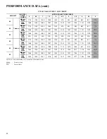
Page 29: ...7 19 85 19 50 20 86 20 62 20 17 SHC 3 13 3 80 4 51 0 85 1 39 1 70 0 97 0 69 0 63 kW 2 92 2 93 2 95 2 96 2 97 2 98 2 98 2 99 3 00 60 TC 23 71 23 48 23 16 24 05 23 98 23 52 24 79 24 47 26 99 SHC 8 11 8 63 8 88 5 97 6 46 6 58 4 65 4 87 5 94 kW 3 17 3 23 3 15 3 21 3 26 3 18 3 23 3 12 3 10 50 TC 21 91 16 69 16 62 16 81 16 98 16 92 17 08 17 24 17 17 SHC 11 51 10 04 9 64 9 77 9 43 8 95 9 30 8 88 8 35 kW ...

Page 30: ...ors of NEMA National Electrical Manufacturers Association design A and B manufactured for use in the United States Ranging from 1 to 200 Hp these continuous duty motors operate on 230 and 460 volt 60 Hz power If a motor does not fit into these specifications the motor does not have to be replaced by an EPACT compliant energy efficient motor Variable speed motors are exempt from EPACT compliance re...

Page 31: ...1 0 56 1275 0 74 0 58 1350 0 67 0 61 1425 0 60 0 63 1500 0 52 0 66 582J 04 HORIZONTAL UNIT DIRECT DRIVE SPEED TORQUE TAP CFM ESP BHP 1 900 0 44 0 22 975 0 32 0 21 1050 0 21 0 20 1125 0 11 0 18 1200 0 04 0 16 1275 1350 1425 1500 2 900 0 50 0 25 975 0 38 0 23 1050 0 26 0 22 1125 0 16 0 20 1200 0 07 0 19 1275 0 00 0 16 1350 1425 1500 3 900 0 66 0 30 975 0 52 0 28 1050 0 39 0 27 1125 0 27 0 26 1200 0 ...

Page 32: ... 0 29 0 73 1800 0 17 0 76 1900 0 05 0 80 2000 0 06 0 83 582J 05 HORIZONTAL UNIT DIRECT DRIVE SPEED TORQUE TAP CFM ESP BHP 1 1200 0 57 0 41 1300 0 40 0 39 1400 0 24 0 37 1500 0 08 0 35 1600 1700 1800 1900 2000 2 1200 0 69 0 46 1300 0 52 0 45 1400 0 36 0 43 1500 0 18 0 40 1600 0 00 0 39 1700 1800 1900 2000 3 1200 0 91 0 56 1300 0 83 0 59 1400 0 74 0 62 1500 0 64 0 64 1600 0 52 0 66 1700 0 39 0 66 18...

Page 33: ...0 0 77 0 95 1875 0 65 0 98 2000 0 41 1 01 2125 0 25 0 88 2250 0 06 1 01 2375 2500 582J 06 HORIZONTAL UNIT DIRECT DRIVE SPEED TORQUE TAP CFM ESP BHP 1 1500 0 36 0 48 1625 0 17 0 45 1750 0 01 0 43 1875 2000 2125 2250 2375 2500 2 1500 0 57 0 60 1625 0 35 0 57 1750 0 15 0 54 1875 0 02 0 51 2000 2125 2250 2375 2500 3 1500 1 02 0 86 1625 0 85 0 87 1750 0 65 0 85 1875 0 44 0 82 2000 0 23 0 80 2125 0 02 0...

Page 34: ...0 1200 1148 1 03 1214 1 23 1276 1 44 1275 1169 1 07 1235 1 28 1296 1 50 1350 1190 1 13 1255 1 33 1425 1211 1 19 1276 1 39 1500 1232 1 25 1297 1 46 Medium static 770 1175 RPM 1 2 BHP max High static 1035 1466 RPM 1 5 BHP max CFM AVAILABLE EXTERNAL STATIC PRESSURE in wg 0 2 0 4 0 6 0 8 1 0 RPM BHP RPM BHP RPM BHP RPM BHP RPM BHP 900 582 0 14 715 0 24 825 0 35 921 0 48 1007 0 63 975 606 0 16 735 0 26...

Page 35: ...50 1354 1 72 1410 1 97 1350 1190 1 13 1255 1 33 1316 1 55 1374 1 78 1429 2 03 1425 1211 1 19 1276 1 39 1337 1 61 1394 1 85 1449 2 09 1500 1232 1 25 1297 1 46 1357 1 68 1415 1 91 1469 2 16 Medium static 770 1175 RPM 1 7 BHP max High static 1035 1466 RPM 2 9 BHP max CFM AVAILABLE EXTERNAL STATIC PRESSURE in wg 0 2 0 4 0 6 0 8 1 0 RPM BHP RPM BHP RPM BHP RPM BHP RPM BHP 900 582 0 14 715 0 24 825 0 35...

Page 36: ...P 1200 1148 1 03 1214 1 23 1276 1 44 1300 1176 1 09 1241 1 30 1400 1204 1 17 1269 1 37 1500 1232 1 25 1297 1 46 1600 1262 1 34 1700 1291 1 44 1800 1900 2000 Medium static 770 1175 RPM 1 2 BHP max High static 1035 1466 RPM 1 5 BHP max CFM AVAILABLE EXTERNAL STATIC PRESSURE in wg 0 2 0 4 0 6 0 8 1 0 RPM BHP RPM BHP RPM BHP RPM BHP RPM BHP 1200 681 0 24 800 0 35 902 0 48 992 0 63 1074 0 78 1300 717 0...

Page 37: ...1291 1 44 1354 1 66 1414 1 89 1470 2 12 1524 2 37 1800 1322 1 55 1384 1 77 1443 2 00 1499 2 25 1900 1352 1 68 1414 1 90 1472 2 13 1528 2 38 2000 1384 1 81 1445 2 04 1502 2 27 Medium static 920 1303 RPM 1 7 BHP max High static 1208 1550 RPM 2 9 BHP max CFM AVAILABLE EXTERNAL STATIC PRESSURE in wg 0 2 0 4 0 6 0 8 1 0 RPM BHP RPM BHP RPM BHP RPM BHP RPM BHP 1200 681 0 24 800 0 35 902 0 48 992 0 63 10...

Page 38: ...RESSURE in wg 1 2 1 4 1 6 1 8 2 0 RPM BHP RPM BHP RPM BHP RPM BHP RPM BHP 1500 1316 1 05 1387 1 17 1454 1 28 1517 1 39 1578 1 50 1625 1353 1 20 1423 1 33 1489 1 46 1750 1391 1 36 1460 1 51 1875 2000 2125 2250 2375 2500 Medium static 1035 1466 RPM 1 5 BHP max CFM AVAILABLE EXTERNAL STATIC PRESSURE in wg 0 2 0 4 0 6 0 8 1 0 RPM BHP RPM BHP RPM BHP RPM BHP RPM BHP 1500 798 0 41 906 0 55 1002 0 71 108...

Page 39: ...46 1750 1391 1 36 1460 1 51 1525 1 65 1875 1430 1 54 1498 1 70 2000 1470 1 73 1537 1 90 2125 1511 1 93 2250 2375 2500 Medium static 1035 1466 RPM 2 9 BHP max High static 1303 1687 RPM 2 9 BHP max CFM AVAILABLE EXTERNAL STATIC PRESSURE in wg 0 2 0 4 0 6 0 8 1 0 RPM BHP RPM BHP RPM BHP RPM BHP RPM BHP 1500 798 0 41 906 0 55 1002 0 71 1088 0 87 1167 1 05 1625 845 0 50 949 0 65 1041 0 81 1125 0 98 120...

Page 40: ... 1207 1164 1121 1078 1035 06 Medium Static 1466 1423 1380 1337 1294 1251 1207 1164 1121 1078 1035 High Static N A N A N A N A N A N A N A N A N A N A N A 04 3 phase Medium Static 1175 1135 1094 1054 1013 973 932 892 851 811 770 High Static 1466 1423 1380 1337 1294 1251 1207 1164 1121 1078 1035 05 Medium Static 1303 1265 1226 1188 1150 1112 1073 1035 997 958 920 High Static 1550 1516 1482 1447 1413...

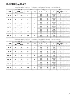
Page 41: ...H 89 4 2 575 3 60 518 633 3 8 37 190 0 5 DD STD 78 4 0 190 0 5 MED 72 1 6 190 0 5 HIGH 77 2 8 582J 05 SINGLE STAGE COOLING WITH SINGLE SPEED INDOOR FAN MOTOR 4 TONS V PH HZ UNIT VOLTAGE COMP 1 OFM ea IFM RANGE RLA LRA WATTS FLA TYPE EFF at Full Load FLA MIN MAX 208 1 60 187 253 21 8 117 325 1 5 DD STD 78 7 4 325 1 5 MED 67 4 9 325 1 5 HIGH 76 7 0 230 1 60 187 253 21 8 117 325 1 5 DD STD 78 7 4 325...

Page 42: ...7 0 230 1 60 187 253 25 0 134 325 1 4 DD STD 78 7 4 325 1 4 MED 76 7 0 208 3 60 187 253 15 9 110 325 1 4 DD STD 78 7 4 325 1 4 MED 89 8 4 325 1 4 HIGH 89 8 4 230 3 60 187 253 15 9 110 325 1 4 DD STD 78 7 4 325 1 4 MED 89 8 3 325 1 4 HIGH 89 8 3 460 3 60 414 506 7 0 52 325 0 9 DD STD 78 4 0 325 0 9 MED 89 4 2 325 0 9 HIGH 89 4 2 575 3 60 518 633 5 1 40 325 0 9 DD STD 78 4 0 325 0 9 MED 77 2 8 325 0...

Page 43: ...2 10 15 10 62 12 15 12 64 582J 05 208 230 1 60 DD STD 37 50 35 128 39 50 37 130 41 60 41 133 43 60 43 135 MED 34 50 32 133 36 50 35 135 39 60 38 138 41 60 40 140 HIGH 36 50 35 158 38 50 37 160 41 60 40 163 43 60 43 165 208 230 3 60 DD STD 26 30 26 94 28 40 28 96 31 40 32 99 33 45 34 101 MED 24 24 30 30 23 23 123 26 26 30 30 26 25 125 29 29 40 40 29 29 128 31 31 40 40 31 31 130 HIGH 27 27 40 40 27 ...

Page 44: ...5 seconds The maximum delay is 3 minutes Once modified the fan off delay will not change back to 45 seconds unless power is reset to the control A LED indicator is provided on the IGC to monitor operation Electromechanical units with an economizer Cooling When free cooling is not available the compressors will be controlled by the zone thermostat When free cooling is avail able the outdoor air dam...

Page 45: ...eheat condenser coil downstream of the evaporator and Motormas ter variable speed control of some or all outdoor fans Opera tion of the revised refrigerant circuit for each mode is described below The Perfect Humidity system provides three sub modes of operation Cool Reheat1 and Reheat2 Cool mode Provides a normal ratio of sensible and latent cooling effect from the evaporator coil Reheat1 Provide...

Page 46: ...L COMPRESSOR OUTDOOR AIR INDOOR LEAVING AIR INDOOR ENTERING AIR DSVx VALVE CSVx VALVE ACUTROL METERING DEVICE REHEAT MODE METERING DEVICE TXV CLOSED VALVE OPEN VALVE CONDENSER COIL PERFECT HUMIDITY COIL EVAPORATOR COIL COMPRESSOR OUTDOOR AIR INDOOR LEAVING AIR INDOOR ENTERING AIR DSVx VALVE CSVx VALVE ACUTROL METERING DEVICE REHEAT MODE METERING DEVICE TXV CLOSED VALVE OPEN VALVE SEQUENCE OF OPERA...

Page 47: ...ll analog inputs 8 Shall accept the following inputs space tempera ture setpoint adjustment outdoor air temperature indoor air quality outdoor air quality compressor lock out fire shutdown enthalpy switch and fan status filter status humidity remote occupancy 9 Shall provide the following outputs economizer variable frequency drive fan cooling stage 1 cool ing stage 2 heat stage 1 heat stage 2 exh...

Page 48: ...elected and installed in compliance with local state and federal codes B 23 81 19 13 B Quality Assurance 1 Unit meets ASHRAE 90 1 minimum efficiency requirements 2 Unit shall be rated in accordance with AHRI Stan dards 210 240 3 Unit shall be designed to conform to ASHRAE 15 4 Unit shall be UL tested and certified in accordance with ANSI Z21 47 Standards and UL listed and certified under Canadian ...

Page 49: ... capability 1 Standard unit shall have a thru the base gas line location using a raised embossed portion of the unit basepan 2 Optional factory approved water tight connection method must be used for thru the base gas connections 3 No basepan penetration other than those authorized by the manufacturer is permitted 9 Electrical connections a All unit power wiring shall enter unit cabinet at a singl...

Page 50: ...nced plate fins mechanically bonded to seamless internally grooved copper tubes with all joints brazed b Evaporator coils shall be leak tested to 150 psig pressure tested to 450 psig and qualified to UL 1995 burst test at 1775 psig c Condenser coils shall be leak tested to 150 psig pressure tested to 650 psig and qualified to UL 1995 burst test at 1980 psig 2 Optional Pre coated aluminum fin conde...

Page 51: ... reset thermal overload protection or circuit breaker c Shall have a maximum continuous bhp rating for continuous duty operation no safety factors above that rating shall be required 2 Direct Drive ECM X13 Evaporator Fan Standard a Multi speed motor with easy quick adjustment settings b Blower fan shall be double inlet type with for ward curved blades c Shall be constructed from steel with a corro...

Page 52: ... vdc CO2 sensor input for IAQ DCV control In this mode dampers shall modulate the outdoor air damper to provide ventilation based on the sen sor input r Compressor lockout temperature on W7220 is adjustable from 45 F to 80 F set at a factory default of 32 F Others shall open at 35 F 2 C and closes at 50 F 10 C s Actuator shall be direct coupled to economizer gear No linkage arms or control rods sh...

Page 53: ...s shall be acceptable e Damper will admit up to 100 outdoor air for applicable rooftop units f Damper shall close upon indoor evaporator fan shutoff and or loss of power g The damper actuator shall plug into the rooftop unit s wiring harness plug No hard wiring shall be required h Outside air hood shall include aluminum water entrainment filter 4 Manual damper a Manual damper package shall consist...

Page 54: ...tions per unit 14 Propeller Power Exhaust a Power exhaust shall be used in conjunction with an integrated economizer b Independent modules for vertical or horizontal return configurations shall be available c Horizontal power exhaust is shall be mounted in return ductwork d Power exhaust shall be controlled by econo mizer controller operation Exhaust fans shall be energized when dampers open past ...

Page 55: ... Can be wired to up to 14 other duct smoke detectors for multiple fan shutdown applications 21 Winter start kit a Shall contain a bypass device around the low pressure switch b Shall be required when mechanical cooling is required down to 25 F 4 C c Shall not be required to operate on an econo mizer when below an outdoor ambient of 40 F 4 C 22 Time Guard a Shall prevent compressor short cycling by...

Page 56: ...continue or change at any time specifications or designs without notice and without incurring obligations Pg 56 Catalog No 04 52582001 01 Printed in U S A Form PDS582J 4 6 06 Replaces PDS582J 4 6 05 2019 Bryant Heating Cooling Systems 1 19 ...

Reviews: