


40
Economizer
2 Position Damper
Unit Without Economizer or
2 Position Damper
C08631
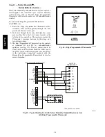
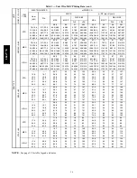
Fig. 54 -- EconoMi$er
t
IV Wiring
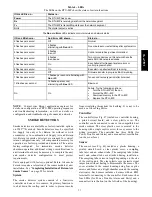
Step 12 — Adjust Factory--Installed Options
Smoke Detectors —
Smoke detector(s) will be connected at the Controls
Connections Board, at terminals marked “Smoke
Shutdown”. Remove jumper JMP 3 when ready to
energize unit.
EconoMi$er IV Occupancy Switch —
Refer to Fig. 54 for general EconoMi$er IV wiring.
External occupancy control is managed through a
connection on the Central Terminal Board.
If external occupancy control is desired, connect a time
clock or remotely controlled switch (closed for Occupied,
open for Unoccupied sequence) at terminals marked
OCCUPANCY on CTB. Remove or cut jumper JMP 2 to
complete the installation.
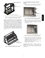
Step 13 — Install Accessories
Available accessories include:
Roof Curb
Thru--base connection kit (must be installed before unit
is set on curb)
Manual outside air damper
Two--Position motorized outside air damper
EconoMi$er IV (with control and integrated barometric
relief)
EconoMi$er2 (without control/for external signal and
integrated barometric relief)
Power Exhaust
Differential dry--bulb sensor (EconoMi$er IV)
Outdoor enthalpy sensor
Differential enthalpy sensor
Electric Heaters
Single Point kits
Low Ambient Controls
Thermostat / Sensors
CO
2
sensor
Louvered hail guard
Phase monitor control
Winter Start kit
Refer to separate installation instructions for information
on installing these accessories.
Pre--Start and Start--Up
This completes the mechanical installation of the unit.
Refer to the unit’s Service Manual for detailed Pre--Start
and Start--up instructions.
Manufacturer reserves the right to discontinue, or change at any time, specifications or designs without notice and without incurring obligations.
E
2010 Bryant Heating & Cooling Systems
D
7310 W. Morris St.
D
Indianapolis, IN 46231
Printed in U.S.A.
Edition Date: 01/10
Replaces: II558J--- 05
Catalog No. II558J---07
558J
***D


