


22
C09276
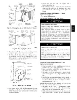
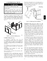
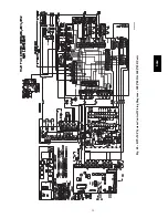
Fig. 27 -- Defrost Control Board (DFB) Location
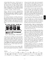
Table 9 – 548J Defrost Board I/O and Jumper Configurations
Inputs
Point Name
Type of I/O
Connection Pin Number
Unit Connection
Note
G Fan
DI, 24---vac
P2---3
LCTB---G
Y1 Cool 1
DI, 24---vac
P2---5
LCTB---Y1
Y2 Cool 2
DI, 24---vac
P2---4
LCTB---Y2
W1 Heat 1
DI, 24---vac
P2---7
LCTB---W1
W2 Heat 2
DI, 24---vac
P2---6
LCTB---W2
R Power
24---vac
P3---1
CONTL BRD---8
C Common
24---vac
P3---2
CONTL BRD---4
DFT1
DI, 24---vac
DFT---1 to DFT---1
DFT 2
DI, 24---vac
DFT---2 to DFT---2
Outputs
Point Name
Type of I/O
Connection Pin Number
Unit Connection
Note
IFO Fan On
DO, 24---vac
P3---9
REHEAT---2
OF OD Fan On
DO, 24---vac
OF
OFR
RVS1
DO, 24---vac
P3---7 to P3---5
Energize in COOL
RVS2
DO, 24---vac
P3---6 to P3---4
Energize in COOL
COMP 1
DO, 24---vac
P3---10
FPT --- REHEAT---6
COMP 2
DO, 24---vac
P3---8
REHEAT---8
HEAT 2
DO, 24---vac
E---HEAT
HC---1 (TB4---1)
COM
24---vac
P3---3
HC---1 (TB4---3)
Configuration
Point Name
Type of I/O
Connection Pin Number
Unit Connection
Note
Select Jumper
24---vac
P1---1
2 Compressor
24---vac
P1---3
Use for 548J***D
Speed--Up Configuration
Point Name
Type of I/O
Connection Pin Number
Unit Connection
Note
Speed---Up Jumper
JMP17
Speed---Up Jumper
JMP18
Jumper for 1--3 secs: Factory Test, defrost runs for 9 secs
Jumper for 5--20 secs: Forced Defrost, defrost runs for 30 secs if DFT2 is open
Reversing valve control — The DFB has two outputs for
unit reversing valve control. Operation of the reversing
valves is based on internal logic; this application does not
use an “O” or “B” signal to determine reversing valve
position. Reversing valves are energized during the
Cooling stages and de--energized during Heating cycles.
Once energized at the start of a Cooling stage, the
reversing valve will remain energized until the next
Heating cycle demand is received. Once de--energized at
the start of a Heating cycle, the reversing valves will
remain de--energized until the next Cooling stage is
initiated.
Compressor control — The DFB receives inputs
indicating Stage 1 Cooling, Stage 2 Cooling (sizes 08 and
09 only) and Stage 1 Heating from the space thermostat or
unit control system (RTU--MP); it generates commands to
start compressors with or without reversing valve
operation to produce Stage 1 Cooling (one compressor),
Stage 2 Cooling (both compressors run) or Stage 1
Heating (both compressors run).
548J


