8
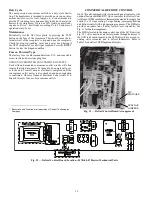
5. If required, remove stator limit switch on aluminum stator.
6. Remove three screws from the heat shield. Retain the heat
shield if a new heat shield has not been ordered.
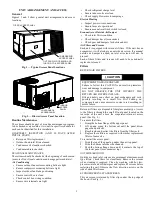
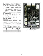
Fig. 11 — Disassembling Motor and Fan Assembly
Reassembly of Motor and Fan Assembly
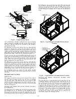
See Fig.12.
1. Install heat shield on motor with three #8-32 x
3
/
8
-in.
thread cutting screws (P/N: AK92AB100). Tighten to
30 in.-lb (3.39 Nm).
2. Place motor on flat surface.
3. If required, install stator limit switch on aluminum stator with
two #10 x
5
/
8
-in. hex head screws (P/N: AL48AM217).
Tighten to 50 in.-lb (5.65 Nm).
4. If required, insert composite ring into aluminum stator
where pegs match up with holes.
5. Line up rectangle key way in the center of stator with
rectangle feature on motor and set stator onto motor.
6. Install four #10-32 x
1
/
2
-in. hex head machine screws
(P/N: AD07AB126) to connect aluminum stator to motor.
Tighten to 23 in.-lb (2.6 Nm).
7. Fit grommet on motor wire harness into keyhole feature on
the side of the stator and pull wire harness out through
grommet.
8. Install rotor on motor by lining up one of 9 holes on com
-
posite rotor with one of 9 holes on motor flange. This can
be done by adjusting motor and the top of the motor hub
and aligning using a
3
/
16
-in. Allen key or similar pin. Press
fan rotor down until it is flush with the motor flange.
9. Set retaining rings (x3) into composite rotor and install 6
#10
-
32 x
1
/
2
-in. hex head machine screws (P/N: AD07AB126)
through the holes in retaining rings. Tighten to 23 in.-lb
(2.6 Nm). It is recommended this screw installation be
done in a star pattern.
10. Align tabs of composite casing with rectangular cutouts on
top of aluminum stator and snap into place.
11. Final assembly should have a small clearance between top of
plastic rotor and underside of casing lip. Spin rotor by hand
to ensure no contact or rubbing between these two parts.
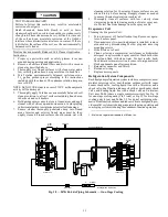
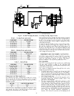
Fig. 12 — Fan System Re-Assembly
1
2
3
4
6
5
2
10
8
6
3
9
4
1
7
7
5


