7
GENERAL NOTES
If the furnace is to be placed on a flammable surface, the floor must be protected by
a fireproof millboard or equivalent. The fireproofing must extend under the furnace and
at least 16” in front of and 8” either side of the fuel loading door.
Pull return air from the same area where supply air is being delivered. Do not pull
return air from a small or closed area where another appliance is located. The resulting
partial vacuum could cause the other appliance to malfunction
.
If return air is installed in a
closed room such as closet, washroom, etc., a 4” under cut door must be installed or a
proper sized return air grille must be installed in the door to allow air to be drawn back
into the heated area.
Your furnace has been tested to determine the minimum safe clearances to com-
bustible materials. The clearances listed below should be adhered to strictly.
Sides of furnace
8”
Rear of furnace
16”
Top of furnace
24 “
Front of furnace
48”
Chimney pipe
12”
Hot air ducting
6” for first 16” from rear of unit, then 2”
FURNACE SET UP
Your Furnace arrives fully assembled and ready to place at a predetermined loca-
tion. You may position the furnace with the door facing left or right or away from the wall.
Position the furnace on a fireproof base, preferable a concrete base. Your furnace weighs
approximately 1400 lbs. Do not install the unit directly onto the ground without adequate
foundation.
After your furnace is adequately set in place, provide electrical service (single outlet
circuit or to a 20 Amp circuit) to the weatherproof junction box located under the left
side of the fan cover. The furnace must be grounded either through the electric cord (third
prong) or by driving a copper coated steel rod (6) six feet into the ground and attaching it
to the base of the furnace with a 14 gauge copper wire. Also, install the provided thermo-
stat at a desired location inside the heated area preferably near the return air. You will
need to provide required thermostat wire from the thermostat to the weatherproof junc-
tion box located under the right side of the fan cover.
Use only a listed 8” Class “A” Chimney. Your furnace is equipped with an 8” double
wall insulated starter section manufactured by Metal-Fab, Inc. of Wichita, Kansas. Use of
a non compatible chimney can lead to unsatisfactory performance, damage to the furnace,
and possible voiding of the warranty. The Metal-Fab Temp Guard 2100 Degree Chimney
and Cap may be purchased from your dealer. Never connect The Bryan Furnace to a
chimney serving another appliance.
After your furnace is set up and before connecting the ductwork to the furnace,
check the fan operation by turning on power to the unit. If fans are not already running,
move the toggle switch located under the left side of the fan cover to the “on” position and
let the fans operate for about five minutes, then turn the toggle switch to the “off” posi-
tion. Next, set your indoor thermostat to a high setting. This should start the combustion
air fan to run. When the fans are running the lights located on the front of the fan cover
should be illuminated. The light on the left side of the fan cover is the main fan indicator
and the one on the right is the combustion air fan indicator.
After assuring that everything is working, start a fire allowing the fan to run until
smoke and fumes no longer come out of the warm air opening . Then attach the supply
and return air duct to the unit.
7
Summary of Contents for 450
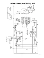
Page 14: ...14 WIRING DIAGRAM MODEL 450 14 ...
Page 19: ...19 MODEL 450 MODEL 300 MODEL 350 ...
Page 21: ...21 ...
Page 22: ...22 ...
Page 23: ...23 ...


