150
HYPERION User Manual
Bruker Optik GmbH
Troubleshooting 7
7.2.3
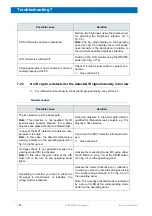
No IR signal is detected or the detected IR signal intensity is too low
☞
For information about how to check the IR signal intensity, see section 4.7.
General causes
CCD of the video camera is saturated.
Reduce the brightness using the thumb wheel
for adjusting the brightness intensity (B in
fig. 3.5)
Note:
The bar graph display on the operating
panel (A in fig. 3.5) indicates the current bright-
ness intensity of the illumination in relation to
the maximum possible brightness intensity.
LCD monitor is switched off.
Switch on the LCD monitor using the ON/OFF
switch (E in fig. 3.17b).
Video signal cable is not connected or not con-
nected properly at the PC.
Check the video signal cable for proper con-
nection.
☞
See section 2.7.4.
Possible cause
Solution
Possible cause
Solution
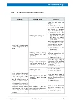
The 4x objective is in the beam path.
Note:
This objective is not qualified for IR
spectroscopic analysis. Reason: It is a glass
objective and glass absorbs mid-infrared light.
Swing an objective in the beam path which is
qualified for IR spectroscopic analysis, e.g. 15x
objective, 36x objective.
In case of the MCT detector, the detector tem-
perature is too high.
Note:
In this case, the detector temperature
warning indicator on the operating panel (G in
fig. 3.4) lights up red.
Cool down the MCT detector with liquid nitro-
gen.
☞
See section 4.4.
IR signal check is not possible because the
viewing mode (VIS) is activated.
Note:
In this case, the green LED at the VIS
button (B in fig. 3.4) on the operating panel
lights.
Activate the measuring mode (IR) using either
the IR button (C in fig. 3.4) or the VIS/IR button
(A in fig. 3.4) on the operating panel.
Depending on whether you want to check the
IR signal in transmission or reflection, the
wrong mode is activated.
Activate the mode (transmission or reflection)
in which you want to check the IR signal using
the corresponding button (E or F in fig. 3.4) on
the operating panel
Note: The currently activated mode is indicated
by a green lit LED at the corresponding mode
button on the operating panel.
Summary of Contents for HYPERION
Page 1: ...HYPERION User Manual I 24319 ...
Page 56: ...54 HYPERION User Manual Bruker Optik GmbH Overview 3 ...
Page 148: ...146 HYPERION User Manual Bruker Optik GmbH Repair and Maintenance 6 ...
Page 168: ...166 HYPERION User Manual Bruker Optik GmbH Specifications A ...
Page 172: ...170 HYPERION User Manual Bruker Optik GmbH Measurement parameters B ...
Page 174: ...172 HYPERION User Manual Bruker Optik GmbH Spare parts and consumables C ...
Page 175: ...173 Bruker Optik GmbH HYPERION User Manual D System diagram ...
Page 176: ...174 HYPERION User Manual Bruker Optik GmbH System diagram D ...


