background image

Blatt
Blatt

Bearb.

11

Urspr

BR 058-31

L.Gemmer

+

Datum

Datum

Ersetzt durch

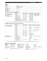
Klemmenplan : X3

1

Änderung

0

7

6

Gepr

Ersatz von

8

9

3

11

15

4

2009-07-13

12

2

=

Name

5

Version

Klemmenplan

Klemme_LTN_DT_F13_003 

X3

Leiste

Funktionstext

Verdrahtung

Verdrahtung

Zielbezeichnung

Zielbezeichnung

Brücke

Brücke

Interne Ziele

Externe Ziele

Platzierung

1

temp.Alarm

1,5mm²

K7:14

5.7

2

=

1,5mm²

K7:12

5.7

3

=

1,5mm²

K7:11

5.7

Summary of Contents for Typ BR 058-31

Page 1: ...Mounting and Operating Manual for Water Chiller Typ BR 058 31 ERL 3000 TA Deckblatt BR 058 31 e doc Ausgabe 27 2010...

Page 2: ...ration and operating 15 9 1 Safety checks before putting into operation 15 9 2 Safety checks during operation 15 9 3 Training and performance 16 9 4 Accident analyses 16 9 5 Management of changes in p...

Page 3: ...No part of this documentation may be reproduced or reprinted duplicated or distributed under usage of electronic systems in whatever form without previous written consent from the companies Lahntechn...

Page 4: ...e based on and according to the following national and international regulations EC Machinery Directive 2006 42 EC EC Low Voltage Directive 2006 95 EC EC EMC Directive 2004 108 EC EC Pressure Equipeme...

Page 5: ...ng maintenance cleaning or fault corrections Wait till parts cool down to under 40 C Use protective gloves Complete aggregate Danger of tripping over through cables and leads Lay out all conduit so th...

Page 6: ...alue and below the min value via a high pressure cut out a low pressure cut out a circuit breaker motor safety switch and fuses a fluid level indicator If the high pressure cut out fails then the circ...

Page 7: ...ons Technical classification as well as electrical circuit diagrams are similarly to be found in the operating instructions Before leaving the factory the unit is tested thoroughly for safety performa...

Page 8: ...Any possible damage is to be reported immediately to the carrier Note the Provisions for Cases of Damage Otherwise the General Terms and Conditions for Supplies and Services of ZVEI Zentralverband der...

Page 9: ...extmarke nicht definiert Always wear safety shoes Take heed of the dimensions and weight in the corresponding datasheets Transport only with pallete bogey fork lift truck or lifting crane Transport th...

Page 10: ...L1 and L2 If all components are in the wrong direction then a phase has to be exchanged at the main connection for all components involved exchange L1 and L2 Provide for protection by fuse s in accor...

Page 11: ...erating position Work on the equipment may only be carried out by trained and qualified persons The appropriate safety and environmental protection regulations are to be observed See declaration of co...

Page 12: ...ply 24 hours before being putting into operation During this time the oil sump heating runs and evaporates the cooling agent away Then after 24 hours have passed the unit can be put into operation Uni...

Page 13: ...C until the system has enough higher pressure so that a circulation of cooling agent in the system is safeguarded Any other or excessive outside the intended limits use thereof is regarded as non desi...

Page 14: ...r contains not only the unit s own safety facilities but also the customer relevant monitoring facilities Details can be sourced from the circuit diagram 8 2 Safety facilities The high pressure switch...

Page 15: ...n the unit before leaving the factory for delivery Due to a change in the operational location a safety health and environment check on location at the customer is recommended before putting into oper...

Page 16: ...needs to be connected to electrical and hydraulic supplies and can be in operation immediately after filling with cooling medium Take note of oil sump heating regulations The recommended medium level...

Page 17: ...reement with the manufacturer Technical documentation for the machine is kept with the manufacturer for at least 10 years All changes to the documented technology are to be agreed upon with the manufa...

Page 18: ...has been changed or has been rendered unrecognisable The cooling equipment has been carefully checked and adjusted in the works Should you nevertheless have a complaint at any time please confidently...

Page 19: ...table trained qualified persons and groups of persons to train qualify such persons and groups of persons if it is so required to ensure that the equipment is used only for the purpose it was designed...

Page 20: ...Operational regulations and safety practices Here there is a recommendation to include the operational regulations into the local regulations Operating personnel must be able to understand the operat...

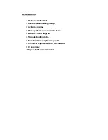
Page 21: ...sional drawing Setup 3 System scheme 4 Pump performance characteristics 5 Electric circuit diagram 6 Troubleshooting table 7 Functional description regulator 8 Chemical requirements for circuit water...

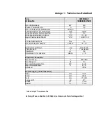
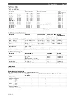
Page 22: ...berdruck bar 18 Hochdruckw chter Aus Ein bar bar 18 13 K ltemittel Typ Menge kg R 134a 2 5 Prim rmedium Trinkwasser Tankinhalt Ltr 150 Schalldruck in 1m Abstand dB A 70 Elektrische Kenndaten Nennspann...

Page 23: ......
Page 24: ...er Filtertrockner filter drier PWT Verdampfer PWT evaporator Lamellenverfl ssiger plate fin condenser Filtermatte air filter Tankentleerung tank drain Wassertank isoliert watertank isolated DIN EN 186...

Page 25: ...4 annex 4 File MTH2 110_6 Diagramm 2 Pumpenkennlinie MTH 2 50 5 pump performance characteristic 10 15 20 25 30 35 40 45 50 0 8 16 24 32 40 48 56 F rderstrom delivery volume dm min F rderh he lift of...

Page 26: ...rsion neutral_LTN_DT_F26_003 Steuerspannung Frequenz Netzanschlu Bruker 230 V 24 V AC 50 Hz Anzahl der Seiten 4 60 kW Stromaufnahme klein von K rzel 8 75 A 2009 07 13 400 V AC BR 058 31 Leistungsaufna...

Page 27: ...um Seitenbeschreibung Inhalt_LTN_DT_F06_001 X Seite 1 Titel Deckblatt 2 Inhaltsverzeichnis 1 16 3 klein Hauptstromkreis 2009 07 13 4 klein Steuerstromkreis 2009 07 13 5 Steuerstromkreis 10 Klemmenplan...

Page 28: ...L1 X1 1 2 3 4 5 6 Q01 M2 0 32 kW 0 74A Ventilator 3 M 5 X1 6 7 8 7x1 5 W4 5 4 1 2 3 1 5 BK 1 5 BK 1 5 BK L1 L2 A1 D Control 1 2 3 4 5 6 F3 1 8 2 5 A 1 9 A I I I 13 14 4 6 U1 V1 W1 PE M3 0 72 kW 1 9 A...

Page 29: ...K7 Temperaturalarm 12 11 14 5 7 A1 A2 Q2 Pumpen 1 2 3 6 3 4 3 6 5 6 3 6 14 13 4 1 R C R4 1 0 rt 1 0 rt 1 0 rot 1 0 rot K6 A3 A4 1 2 K5 A1 A2 Q1 K hlung 1 2 3 2 3 4 3 2 5 6 3 2 2 L1 3 L1 2 L1 1 K1 1 7x...

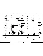
Page 30: ...9 3 11 10 4 2009 07 13 5 2 Name 5 Version 00 0 C Temperaturalarm 24 V 0 V 1 0 1 2 F5 2A K1 A1 L3 1 A2 L3 2 112 L2 4 111 L2 3 Spannungsversorgung 3x1 0qmm 5 3 W13 1 Spannungsversorgung 3x1 0qmm 5 3 W13...

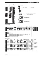
Page 31: ...Ziele Externe Ziele Platzierung M2 1mm 5 Ventilator 1mm U 3 4 M2 1mm 6 1mm V 3 4 M2 1mm 7 1mm W 3 4 8 M2 1mm Ventilator PE M3 U1 1mm 9 Pumpe 1 5mm F3 2 3 6 M3 V1 1mm 10 1 5mm F3 4 3 6 M3 W1 1mm 11 1...

Page 32: ...erung 1 1mm 1 Hochdruckschalter 1mm Q2 14 4 1 2 Hochdruckschalter 1mm 2 4 1 1 0mm K5 1 4 3 1 1mm 3 Niederdruckschalter 5 2 1mm 7 Magnetventil Bypass Niederdruck 3 1mm x2 1mm K5 2 4 3 6 1mm PE 4 2 Nied...

Page 33: ...7 6 Gepr Ersatz von 8 9 3 11 15 4 2009 07 13 12 2 Name 5 Version Klemmenplan Klemme_LTN_DT_F13_003 X3 Leiste Funktionstext Verdrahtung Verdrahtung Zielbezeichnung Zielbezeichnung Br cke Br cke Intern...

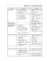
Page 34: ...eat development in user a Remove dirt b Inform refrigeration specialist c b Check pump pipework d Provide for sufficient air supply exhaust e Look for abnormal heat source High pressure switches off a...

Page 35: ...so reqd g Check pump h Increase ambient temperature Compressor switches off Motor circuit breaker has responded because compressor uses too much current Pump motor is overheated or defective Inform r...

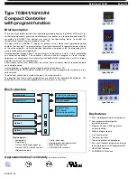
Page 36: ...the dimensional unit ramp function and manual operation Simple operation through 4 keys The instruments can be used as 2 state 3 state modulating or continuous controllers The controller software inc...

Page 37: ...old cancel Timer start stop The logic functions can be combined with one another only through the setup program Functions of the outputs Analog input variables Math Process value Setpoint Ramp end val...

Page 38: ...ntegral component of the controller output signal Cycle time 0 to 999 9 sec 20 0 sec When using a switched output the cycle time should be chosen so that the energy flow to the process is as continuou...

Page 39: ...internal Designation Connection Measuring range Measuring accuracy Ambient temperature error 3 4 wire 2 wire Pt100 EN 60751 factory setting 2 wire 3 wire 4 wire 200 to 850 C 0 05 0 4 50 ppm C Pt500 E...

Page 40: ...tage for 2 wire transmitter for type 703042 43 44 voltage electrically isolated not stabilized 17V DC at 20mA load 25V DC with no load Controller type 2 state controller factory setting 3 state contro...

Page 41: ...0 Sensor type Temperatur range1 1 This is the sensor temperature range The approval of the device does only apply to the temperature ranges listed on page 4 10 Fitting length mm Process connection Res...

Page 42: ...t of strip 1 for analog input 2 Logic input 2 bin1 bin2 GND Logic output 3 Out3 Out4 GND Logic output level 12V or 18V see order details Logic input 1 or Logic output 4 configurable 1 2 4 3 Analog inp...

Page 43: ...t3 Logic output 3 Out4 Logic output 4 GND Logic output level 12V or 18V see order details Logic input 2 1 2 4 3 Analog input 2 logic inputs Analog output Relay changeover 2 relays make PROFIBUS RS422...

Page 44: ...nimum spacing of panel cut outs Type horizontal vertical without setup connector 703041 703042 portrait format 703043 landscape fmt 703044 11mm 11mm 30mm 11mm 30mm 30mm 11mm 30mm with setup connector...

Page 45: ...gic inputs 2 1 X X 6 6 6 Solid state relay 1A 2 2 X X 7 7 7 RS422 485 interface 1 1 X X 8 8 8 Profibus DP interface 1 1 X X Supply voltage 2 3 110 240V AC 15 10 48 63Hz 2 5 AC DC 20 30V 48 63Hz 1 7030...

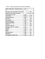
Page 46: ...0 2 Total hardness of water dH 6 Conductivity m S cm 10 500 Filtered substances mg l 30 Chlorides mg l 100 Free chlorine mg l 0 5 Hydrosulphide H2S mg l 0 05 Ammonia NH3 NH4 mg l 2 Sulphate mg l 100...

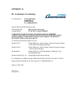
Page 47: ...mpatibility and RL 97 23 EC relating to pressure equipment The following harmonized standards were used DIN EN 12100 1 Safety of Machinery Basic Concepts General Principles for Design Part 1 Basic Ter...

Page 48: ...M16 RV16 1 St ck 3703579900030 filter drier HM 163 sm Art Nr 2134410050 1 St ck 3902509900013 expansions valve 068U 200 700 R134a 1 St ck 3301989900095 P W T B8 x 16 Anschl 2x22mm L t 2x AG 1 St ck 3...

Reviews: