background image

53

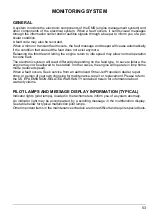
MONITORING SYSTEM

GENERAL

A system monitors the electronic components of the EMS (engine management system) and

other components of the electrical system. When a fault occurs, it sends visual messages

through the information center and/or audible signals through a beeper to inform you of a par-

ticular condition.
A fault code may also be recorded.
When a minor or transient fault occurs, the fault message and beeper will cease automatically

if the condition that caused the fault does not exist anymore.
Releasing the throttle and letting the engine return to idle speed may allow normal operation

to come back.
The electronic system will react differently depending on the fault type. In severe failure, the

engine may not be allowed to be started. In other cases, the engine will operate in limp home

mode (reduced speed).
When a fault occurs, Seek service from an authorized 

Rotax 

Jet Propulsion dealer, repair 

shop, or person of your own choosing for maintenance, repair, or replacement. Please refer to 

the US EPA EMISSION-RELATED WARRANTY contained herein for information about 

warranty claims.

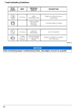
PILOT LAMPS AND MESSAGE DISPLAY INFORMATION (TYPICAL)

Indicator lights (pilot lamps), located in the tachometers, inform you of a system anomaly.
An indicator light may be accompanied by a scrolling message in the multifunction display.

See table below for typical malfunction pilot lamps.
Other important items in the maintenance schedule are more difficult and require special tools.

Summary of Contents for Rotax 4-TEC 150

Page 1: ...s Manual thoroughly It contains important safety information Minimum recommended operators age 16 years old Keep this Operators Manual in the boat 2015 Bombardier Recreational Products Inc All rights reserved TM and the BRP logo are trademarks of Bombardier Recreational Products or its affiliates ...

Page 2: ... CALIFORNIA PROPOSITION 65 WARNING WARNING This product contains or emits chemicals known to the state of California to cause cancer and birth defects or other reproductive harm ...

Page 3: ...lity of the Boat and Towing 17 Passenger Safety 18 Fueling 19 IMPORTANT ON PRODUCT LABELS 20 Label Location 20 Labels 20 PRE RIDE INSPECTION 21 BREAK IN INSPECTION 26 MAINTENANCE SCHEDULE 28 ROTAX JET PROPULSION PERIODIC MAINTENCANCE SCHEDULE 29 MAINTENANCE PROCEDURES 31 General 31 Engine Oil 31 ENGINE COOLANT 33 Ignition Coils 34 EXHAUST SYSTEM 35 BOAT CARE 36 STORAGE 37 PRESEASON PREPARATION 39 ...

Page 4: ...BREAK IN 56 Operation 56 SPECIAL PROCEDURES 57 Jet Pump Water Intake and Impeller Cleaning 57 In the Water Towing 57 ...

Page 5: ...Safety And Warranty Information ...

Page 6: ...tions It is indis pensable for the proper use of the product Keep this Operators Manual in the boat as you can refer to it for things such as mainte nance troubleshooting and instructing others Note that this Manual is available in several languages In the event of any discrepancy the English version shall prevail If you want to view and or print an extra copy of your Oper ators Manual simply visi...

Page 7: ...fashion Observe the instructions on all safety labels They are there to help assure that you have a safe and enjoyable outing Riding with passenger s or pulling other boats tubes a skier or a wakeboarder makes the boat handle differently and requires great er skills In shallow water proceed with caution and at very low speeds Grounding or abrupt stops may result in injury to you your passengers or...

Page 8: ... Damage resulting from external damage accident submersion water ingestion fire theft vandalism or any act of God Operation without proper fuel oil or lubrication or with fuels oils or lubricants which are not suitable for use with the Product see the Operators Manual Damage resulting from rust or corrosion Damage caused from cooling system blockage by foreign material Damage resulting from sand o...

Page 9: ...ol Warranty Statement contained herein In cases where the delivery date is not established to BRP s satisfaction the date of sale will be used to determine the warranty start date The repair or replacement of parts or the perfor mance of service to Product under this warranty does not extend the life of this limited warranty beyond its original expiration date For all Rotax Jet Propulsion System g...

Page 10: ...tured 8 Transfers If the ownership of Product is transferred during the warranty coverage period this warranty shall also be transferred and be valid for the remaining coverage period provided that BRP is notified of such transfer of ownership in the following way 1 The former owner contacts BRP or a Dealer and gives the coordinates of the new owner or 2 BRP or a Dealer receives a proof that the f...

Page 11: ...o the warranty claim 4 Maintenance that was performed more frequently than BRP specify 5 Anything that is BRP fault or responsibility 6 The use of any fuel that is commonly available where the equipment operates unless BRP written maintenance instructions state that this fuel would harm the equipment s emission control system and operators can readily find the proper fuel See maintenance informati...

Page 12: ...ols Vacuum control diaphragms Control cables Control linkages Purge valves Vapor hoses Liquid vapor separator Carbon canister Canister mounting brackets Carburetor purge port connector 4 Emission related components also include any other part whose only purpose is to reduce emissions or whose failure will increase emissions without significantly degrading engine equipment performance As related to...

Page 13: ...bean Islands all Central American countries and all other South American coun tries T 95 48 46 1442 Mexico T 33 22 82 7700 SCANDINAVIA Finland Norway Sweden T 358 1632 08 132 RUSSIA CENTRAL AND EASTERN EUROPE COMMONWEALTH OF INDEPENDENT SATES CEE CIS Russia Turkey Romania Hungary Poland Slovenia and all other Eastern European countries T 420 232 007 000 WESTERN EUROPE MIDDLE EAST AND AFRICA WEMEA ...

Page 14: ...t or left and in close proximity to the required location of the California Assigned Vessel Number The label has 4 stars A hang tag provided with your boat describes the meaning of the star rating system Dealer lo cated in California has the responsibility of displaying the hangtag on a visible location to each boat equipped with Rotax Inboard Jet Propulsion System and to identify the correspondin...

Page 15: ... One Star Low Emission engines Three Stars Ultra Low Emission The three star label identifies engines that meet the Air Resources Board s Personal Water craft and Outboard marine engine 2008 exhaust emission standards or the Stern drive and In board marine engine 2003 exhaust emission standards Engines meeting these standards have 65 lower emissions than One Star Low Emission engines Four Stars Su...

Page 16: ...warranty the part will be repaired or replaced by BRP Parts Covered For Boats Equipped With Rotax Inboard Jet Propulsion Systems The emission warranty covers damage to other engine components that is caused by the fail ure of a warranted part The BRP Operators Manual provided contains written instructions for the proper maintenance and use of your Inboard Jet Propulsion System All emission warrant...

Page 17: ... your failure to ensure the performance of all scheduled maintenance As the owner of a Rotax Inboard Jet Propulsion System you should however be aware that BRP may deny you warranty coverage if your engine s or a part has failed due to abuse neglect improper maintenance or unapproved modifications You are re sponsible for presenting your engine to an authorized BRP Dealer as soon as a problem ex i...

Page 18: ...ross the chest head aches drowsiness nausea dizziness fatigue vomiting collapse and convulsions If any of these symptoms are evident begin treatment immediately Prompt action can make the differ ence between life and death Evacuate the area and move the victim to fresh air Administer oxygen if available and get medical help Open all canvas enclosures to ventilate the area Investigate the source of...

Page 19: ...e the chances of CO accumulation While underway CO concentrations can increase by backdrafting or the station wagon ef fect Backdrafting is caused by factors such as relative wind direction speed or the bow be ing too high To prevent this open canvas whenever possible to provide positive airflow through the hull WARNING Engine exhaust fumes contain carbon monoxide CO which can accumulate in and ar...

Page 20: ...is not a gas fuel vapor detector Gas fuel vapor detectors do not monitor the buildup of CO in an enclosed area DO NOT Operate your Boat Without Performing the Following Checklist Each Boating Use B00061 OPERATION SIGN Make sure you and your passengers know where exhaust outlets are located on the vessel Educate all passengers about the symptoms of CO poisoning and where CO may accumulate When dock...

Page 21: ... the boat and in the immediate boating ar ea While your boat has the capacity of operating at high speeds it is strongly recommended that high speed operation only be applied when ideal conditions exist and are permitted Higher speed operation requires a higher de gree of skill and increases the risk of severe injuries In shallow water proceed with caution and at very low speed Grounding or abrupt...

Page 22: ...enger s should be properly seated before starting or moving the boat All passenger s should be instructed to use the handholds or seat straps provided When accelerating a boat with a passen ger s whether from a complete stop or while underway always do so progressively Fast acceleration may cause your passenger s to lose their balance or grip and strike something in the boat or fall out of the boa...

Page 23: ...Be very careful when fueling and adhere to the fueling procedures described below in this Operators Manual and those given to you by the marina Know the capacity of the fuel tank Avoid fuel ing at night except under well lighted condi tions Gas spills are not noticeable in the dark Do not carry spare fuel or flammable liquids in any of the storage or engine compartments NOTICE Always use fresh gas...

Page 24: ...lly before operating your boat IMPORTANT The illustration indicates the approximate locations of the various labels A dashed line indicates the label is not on the outer surface and cover must be opened to see the label s LABEL LOCATION LABELS 1 Cover 0460111 1 Labels 0460111 Label ISO 13592 0460111 1 1 Typical Model Serial 0460810 Typical when applicable Emissions Control Information 0460111 ...

Page 25: ...pment required by local laws Perform a pre ride inspection before each ride to detect potential problems during operation The pre ride inspection can help you monitor wear and deterioration before they become a problem Correct any problems that you discover to reduce the risk of a breakdown or accident WARNING Engines must be off and the tether cord removed from engine cut off switch except where ...

Page 26: ...eration Steering Check operation Bilge blower Turn ON bilge blower for 5 minutes to ventilate bilge Instrumentation Check operation Mandatory safety boating equipment Ensure all required safety equipment is on board Storage compartment covers Ensure they are closed and latched Navigation lights Check operation Engine s start stop switch Check operation for starting and stopping engine s Engine cut...

Page 27: ... Check operation Bilge blower Turn ON bilge blower for 5 minutes to ventilate bilge Instrumentation Check operation Mandatorysafetyboating equipment Ensure all required safety equipment is on board Storage compartment covers Ensure they are closed and latched Navigation lights Check operation Engine s start stop switch Check operation for starting and stopping engine s Engine cut off switch Check ...

Page 28: ...24 Safety And Warranty Information NOTES ...

Page 29: ...25 Inspections and Maintenance ...

Page 30: ...d must not be neglected IMPORTANT The break in inspection is at the expense of the boat owner We recommend that this inspection be signed by an authorized Rotax Jet Propulsion dealer repair shop or person of your choosing _____________________________ Date of inspection _____________________________ Authorized dealer repair shop or person signature _____________________________ Name of authorized ...

Page 31: ...FUEL SYSTEM Fuel lines connections and pressure relief valve Fuel system leak test Throttle body Throttle cable ELECTRICAL SYSTEM Spark plugs Electrical connections and fastening ignition system starting system fuel injectors fuse boxes etc Engine cut off switch Main battery cut off switch STEERING SYSTEM Steering cable and connections Steering nozzle bushings PROPULSION SYSTEM Shift lever cable a...

Page 32: ...information please refer to the US EPA EMISSION RELATED WARRANTY contained herein Proper maintenance is the owner s responsibility A warranty claim may be denied if among other things the owner or operator caused the problem through improper maintenance or use You must follow the instructions for fuel requirements in the fueling section of this manual Even if gasoline containing greater than ten v...

Page 33: ...for corrosion protection 8 Inspect each month every two weeks in salt and change when necessary TO BE PERFORMED BY EVERY 200 HOURS OR 2 YEARS EVERY 100 HOURS OR PRE SEASON FIRST 25 HOURS PART TASK ENGINE Engine oil and filter R R 1 RS Rubber mounts I I O RS Corrosion protection 3 L 4 O EXHAUST SYSTEM Exhaust system including hoses fasteners components and leaks I I C 5 O RS Exhaust system flushing...

Page 34: ... OR 2 YEARS EVERY 100 HOURS OR PRE SEASON FIRST 25 HOURS PART TASK ELECTRICAL SYSTEM Test the engine cut off switch and the monitoring beeper at first 50 hours and every 100 hours or once a year I I Spark plugs I I R RS Ignition coils I I L RS Electrical connections and fastening visual inspection I I RS STEERING SYSTEM Steering cable and connections I 4 I O Steering nozzle bushings I 4 I O RS PRO...

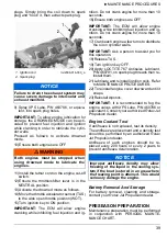
Page 35: ... you can be injured by hot parts moving parts electricity chemicals or other hazards WARNING Should removal of a locking device be required e g lock tabs self locking fas teners etc always replace it with a new one CAUTION Some components in the engine com partment may be very hot NOTICE These engines have been developed and validated using the BRP XPS Synthetic blend oil BRP recommends the use of...

Page 36: ...e for 30 seconds before stop ping 3 Stop engine 4 Wait at least 30 seconds 5 Pull dipstick out and wipe clean 6 Reinstall dipstick push in completely 7 Remove dipstick and read oil level It should be between marks NOTICE Check level frequently and refill if neces sary Operating the engines with improper oil levels may severely damage engines TYPICAL 1 Dipstick 2 Oil cap B00064 NOTICE Never run eng...

Page 37: ...boat on a level surface coolant should be between MIN and MAX level marks for each coolant reservoir when each engine is cold IMPORTANT The boat is considered level when it is in water When boat is on a trailer block the wheels and raise the bow slightly with the trailer jack if so equipped until the bumper rail is level Add coolant to have the level between marks as required Use a funnel to avoid...

Page 38: ... shown to act as a water barrier Wipe off the excess 5 Apply DOW CORNING 111 P N 460796 or equivalent on rubber seal contact area Ignition Coil Installation IMPORTANT Prior to inserting the ignition coil on its spark plug apply sealant as de scribed in IGNITION COIL LUBRICATION 1 Install coil in cylinder head hole 2 Push the ignition coil down to securely in stall it on the spark plug tip NOTICE D...

Page 39: ...den hose to the connector lo cated at the rear of boat on jet pump sup port Do not open water tap at this time IMPORTANT Use optional Flushing Adapter P N 460711 with a quick connect adapter to ease garden hose installation A hose pincher is NOT required to flush engine TYPICAL 1 Seal properly seated smr2009 032 004 WARNING Perform this operation in a well venti lated area WARNING When operating t...

Page 40: ...ul Water or Salt Water Use When the boat is operated in foul water and particularly in salt water additional care must be taken to protect the boat and its compo nents Rinse trailer and boat s hull bilge area with fresh water Never use a high pressure washer to clean the bilge USE LOW PRESSURE ONLY CAUTION Certain components in the engine com partment may be very hot Direct contact may result in s...

Page 41: ...f your choosing Intercooler Draining It is important to expel any trapped water that may have accumulated from condensation in the intercooler of each engine Proceed as follows 1 Open the engine cover 2 Ensure there is an alignment line drawn on the intercooler outlet hose This will ensure the hose is not twisted or kinked on rein stallation 3 Loosen the clamp retaining the intercooler outlet hose...

Page 42: ...brication IMPORTANT Both engines must be internal ly lubricated for the storage period 1 Open the engine compartment lid 2 Remove storage tray 3 Remove dipstick 4 Remove engine cover 5 Reinstall dipstick 6 Expel water from the exhaust system and intercooler as follows 7 Remove ignition coils Refer to MAINTE NANCE PROCEDURE 8 Remove spark plugs IMPORTANT After loosening the spark plugs a coil may b...

Page 43: ...Turn ignition key OFF 20 Apply LOCTITE 767 Antiseize Lubricant P N 460791 on spark plug threads then re install them 21 Lubricate and reinstall ignition coils Refer to MAINTENANCE PROCEDURES 22 To reinstall engine cover downward until it snaps 23 Reinstall dipstick IMPORTANT It is recommended to fog the engine valves with XPS Lube P N 460786 or equivalent Contact your authorized Rotax Jet Propulsi...

Page 44: ...dealer perform preseason maintenance preparation at the same time that any safety related facto ry campaigns are performed by the autho rized Rotax Jet Propulsion dealer WARNING Only perform procedures as detailed in the PERIODIC MAINTENANCE CHART It is recommended that the assistance of an authorized Rotax Jet Propulsion dealer be periodically obtained on other components and systems not covered ...

Page 45: ...41 Technical Information and Specifications ...

Page 46: ...rescribed changes such as altitude adjustments for ex ample Owner s Responsibility The owner operator is required to have in board maintenance performed to maintain emission levels within prescribed certification standards The owner operator is not to and should not allow anyone to modify the in board in any manner that would alter the horsepower or allow emissions levels to ex ceed their predeter...

Page 47: ... TECHNICAL INFORMATION U S Environmental Protection Agency Certification Division Gasoline Engine Compliance Center 2000 Traverwood Drive Ann Arbor MI 48105 USA EPA INTERNET WEBSITE http www epa gov otaq ...

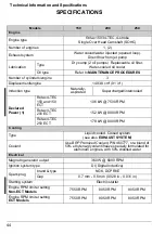
Page 48: ...ed intercooled Declared Power 1 Rotax 4 TEC 150 and 150 ECT 106 kW 7500 RPM Rotax 4 TEC 200 ECT 152 kW 8000 RPM Rotax 4 TEC 250 ECT 179 kW 8000 RPM Cooling Type Liquid cooled Closed system see also EXHAUST SYSTEM Coolant Use BRP Premixed Coolant P N 460777 or a blend of 50 ethylene glycol antifreeze specially formulated for aluminum engines with 50 distilled water Electrical Magneto generator outp...

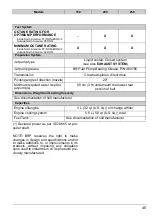
Page 49: ...ide North America 87 RON MON 2 Outside North America 92 RON Propulsion System Jet pump type Liquid cooled Closed system see also EXHAUST SYSTEM Jet pump grease BRP Jet Pump Bearing Grease P N 460785 Transmission Crowned splines direct drive Pivoting angle of direction nozzle 20 Minimum required water level for jet pump s 90 cm 3 ft underneath the lowest rear portion of hull Dimensions Weight and L...

Page 50: ...46 Technical Information and Specifications NOTES ...

Page 51: ...47 Troubleshooting Guidelines ...

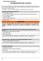
Page 52: ...o not charge or boost the battery while installed in the engine compartment Electrolyte is poisonous and capable of causing severe burns NO BEEPS ARE HEARD WHEN INSTALLING THE TETHER CORD ON ENGINE CUT OFF SWITCH 1 Main battery cut off switch is turned OFF Verify and turn ON 2 Battery discharged Have the battery charged or replaced by an authorized Rotax Jet Propulsion dealer repair shop or person...

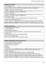
Page 53: ...nformation about warranty claims ENGINE TURNS SLOWLY 1 Loose battery cable connections Check clean tighten 2 Discharged or weak battery Have the battery charged or replaced by an authorized Rotax Jet Propulsion dealer 3 Bad grounds Refer to an authorized Rotax Jet Propulsion dealer 4 Worn starter or related parts Refer to an authorized ROTAX Jet Propulsion dealer ENGINE TURNS NORMALLY BUT WILL NOT...

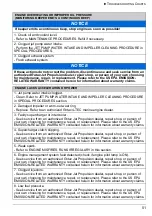
Page 54: ...Engine management system fault detected check if engine pilot lamp is ON Seek service from an authorized Rotax Jet Propulsion dealer repair shop or person of your own choosing for maintenance repair or replacement Please refer to the US EPA EMISSION RELATED WARRANTY contained herein for information about warranty claims ENGINE SMOKE 1 Oil level too high Seek service from an authorized Rotax Jet Pr...

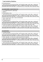
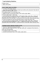
Page 55: ...ing for maintenance repair or replacement Please refer to the US EPA EMISSION RELATED WARRANTY contained herein for information about warranty claims 4 Supercharger clutch slipping Seek service from an authorized Rotax Jet Propulsion dealer repair shop or person of your own choosing for maintenance repair or replacement Please refer to the US EPA EMISSION RELATED WARRANTY contained herein for info...

Page 56: ...eplacement Please refer to the US EPA EMISSION RELATED WARRANTY contained herein for information about warranty claims 4 Engine management system fault detected check if engine pilot lamp is ON Seek service from an authorized Rotax Jet Propulsion dealer repair shop or person of your own choosing for maintenance repair or replacement Please refer to the US EPA EMISSION RELATED WARRANTY contained he...

Page 57: ...m will react differently depending on the fault type In severe failure the engine may not be allowed to be started In other cases the engine will operate in limp home mode reduced speed When a fault occurs Seek service from an authorized Rotax Jet Propulsion dealer repair shop or person of your own choosing for maintenance repair or replacement Please refer to the US EPA EMISSION RELATED WARRANTY ...

Page 58: ...54 Troubleshooting Guidelines B00070 NOTICE If the monitoring beeper continuously sounds stop engine as soon as possible ...

Page 59: ...55 Break In and Special Procedures ...

Page 60: ...by a break in strategy programmed into the ECM Depending on the engine model and boat combination maximum engine speed could be reduced to 7000 RPM or less Over the initial seven hours of operation the engine speed limitation is progressively re duced At the conclusion of seven hours run time maximum engine speed is available NOTICE Carefully follow the instructions in this section Failure to do s...

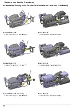
Page 61: ...on sys tem If not refer to OUT OF WATER CLEANING Out of Water Cleaning From underneath boat manually clean water intakes area If the system is still clogged re fer to an authorized Boats dealer for servicing IN THE WATER TOWING Maximum recommended towing speed is 24 km h 15MPH IMPORTANT On models with twin engines this procedure must be followed for both en gines The cooling water supply hose to t...

Page 62: ...s Rotax 4 TEC 150 ECT 1 Hose Pincher Tool P N 460717 Rotax 4 TEC 200 ECT 1 Hose Pincher Tool P N 460717 Rotax 4 TEC 250 ECT requires 2 1 Hose Pincher Tool P N 460717 Rotax 4 TEC 150 1 Hose Pincher Tool P N 460717 Rotax 4 TEC 200 1 Hose Pincher Tool P N 460717 Rotax 4 TEC 250 1 Hose Pincher Tool P N 460717 ...

Page 63: ......
Page 64: ...s Manual thoroughly It contains important safety information Minimum recommended operators age 16 years old Keep this Operators Manual in the boat 2015 Bombardier Recreational Products Inc All rights reserved TM and the BRP logo are trademarks of Bombardier Recreational Products or its affiliates ...

Reviews: