


15
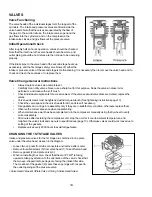
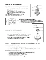
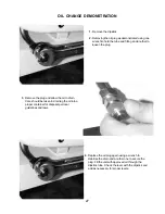
CHANGING THE 2ND STAGE VALVES
Both the pressure and intake valves can be serviced from the outside.
• Remove two captive nuts (1) and springwashers (2).
• Remove plate (3).
• Remove valves (4) and (7) using two screwdrivers as shown in the
diagram below.
• Assemble in reverse sequence.
Position springwashers (2) with curved side facing up.
Fasten nuts so that plate (3) is parallel to the valve head.
Torque as specified.
1.Nut 2.Springwasher 3.Plate 4.Pressure Valve 5.O-ring
6.Valve Head 7.Intake Valve 8.Valve Head Screw
Removal of 2nd and 3rd stage valves:
• Place two screwdrivers into the groove of pressure valve body. If
necessary turn valve loose using a 13mm wrench on the flat surfaces.
• Lift out pressure valve together with o-ring.
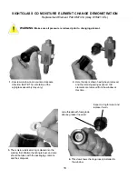
CHANGING THE 3RD STAGE VALVES
• On this valve head, the valves are arranged on the upper and lower side
due to the small diameter of the cylinder.
• For removal and installation of the intake valve (4) use the special tool
(part # 004555) which is part of the tool set provided with the unit.
•Pressure valve (3) is merely inserted into valve head (5). It is sealed by
the o-ring (2), and fixed to the valve head by bolt (1).
CHANGE INTAKE AND PRESSURE VALVES OF THE 3RD STAGE AS A SET ONLY
Removal of the 3rd stage pressure valve (3).
• Unscrew screw (1) a couple turns.
• Remove allen screws (7), take off valve head cover (6).
• Using screwdrivers as shown above, lifting out the pressure valve (3) together with the O-ring (2).
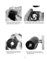
Reinstall pressure valve (3) in reverse sequence:
• Put o-ring (2) into valve head (5). Check o-ring for abrasion, and replace if worn.
• Insert pressure valve (3). Install valve head cover (6).
• Fasten valve head with allen screws (7) and washers (8).
• Screw in and torque stud (1) as specified.
Summary of Contents for YP25DF
Page 2: ...2 ...
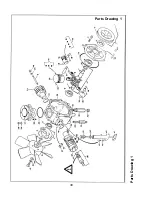
Page 30: ...30 Parts Drawing 1 Parts Drawing 1 ...
Page 32: ...32 Parts Drawing 2 Parts Drawing 2 ...
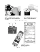
Page 35: ...35 Figure 5 Black Filter Tower Figure 5 Black Filter Tower ...
Page 44: ...44 NOTES ...