background image

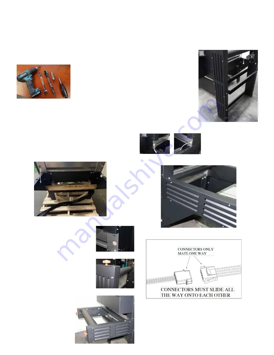
Step 6: Remove the cover plates from the feed extension 

using a 1/4” nut driver.  Remove the 3/8-16 nuts, washer 

and bolts from the feed extension.  Remove the 3/8-16 bolts 

and washers the front end of the oven.  There are triangular 

trusses for supporting the 

feed end of the oven.  Sit 

the extension on top of these 

trusses.  

Feed the motor and photoeye 

wires through and connect 

the ends.  See Figure 2.  

Use the hardware to secure 

the feed end to both the 

end of the oven andf to the 

trusses.  Secure with the 

wrench.

Unpacking and Assembly

Tools needed

•  9/16 open end wrench or ratchet wrench

•  1/4” nut driver, manual or powered

•  screwdriver bit

Step 1: Remove the feed end of the oven from the top of 

the machine.

Step 2: Remove the exit extension from the crate under the 

control panel.

Step 3: Remove the wooden securing board from undeer 

the machine using a powered screwdriver.  Remove the 

main body from the skid and place into desired position.  

Place the machine into a stable location.

Step 4:  Remove the 3/8-16 hardware 

from the exit end of the machine.  

Step 5: Remove the cover plates 

from the exit extension using a 1/4” 

nut driver.  Use the 3/8-16 bolts and 

washers to attach the exit extension to 

the end of the oven.  The exit is to the 

left of the control panel.  Tighten with 

a 9/16” wrench.  Reattach the cover 

plates.

Figure 2: Connecting belt sensor wires

Summary of Contents for DragonAir DAK-2408

Page 1: ...rofits The new DragonAir line of curing systems is designed for water based digital printing in fast paced shops The Dragon Air Core Technology ensured consistent and complete curing on all garments Brown Manufacturing Group Inc 4661 Stafford SW Wyoming MI 49548 616 249 0200 fax 616 249 3211 www brownmfg net customerservice brownmfg net 20 00 March 2022 DAK 2408 ...

Page 2: ...tchet wrench 1 4 nut driver manual or powered screwdriver bit Step 1 Remove the feed end of the oven from the top of the machine Step 2 Remove the exit extension from the crate under the control panel Step 3 Remove the wooden securing board from undeer the machine using a powered screwdriver Remove the main body from the skid and place into desired position Place the machine into a stable location...

Page 3: ...supply wires to the main terminals marked L1 and L2 Ensure that 208 240 VAC is being delivered through the breaker by testing across these lines Ensure that 115VAC is being delivered between each of the power lines and the neutral line Main power lines should be rated to carry 125 of the full load amperes FLA Machine Adjustments Belt Tension Apply enough tension to keep the belt from slipping on t...

Page 4: ...t the furthest left dial position the fan is off At the first click the fan is full speed Turned to the right it is at it s lowest Recommendation is the dial is turned all the way to the right Step 4 Adjust the percentange of bump heat This adjusts the first heaters in the chamber with the goal of raising the shirt temperature quickly for faster cure This bump gets very hot 20 bump is suggested St...

Page 5: ...es are warranted for seven 7 years from the date of Installation iv Machine chassis are warranted for fifteen 15 years from the date of Installation frames rollers linear rails bearings gears plastic and metal with this Productpurchase WHAT IS NOT COVERED This warranty does not cover 1 Physical damage to thisProduct 2 Damage caused by improper Installation improper or abnormal use misuse neglect o...

Page 6: ...ble ZWIRE120 GND L1 L2 BKR3 ZBRKR101 D 3 4A BRD1 ZMTR111 Main Controller DC DC MOT1 ZGMTR113 Belt Motor External 4 18 2 MOT2 ZFAN100 B Control Panel Cooling Fan CONT2 ZCONT100 Fan Speed Control MOT3 ZFAN105 Convection Air Fan External 2 5 CONT3 ZCONT132 Temperature Control DC DC TCPL TCPL 17 16 SENSE1 ZSENSE102 Located in heater rack IR3 ZHTR101 2200W IR1 ZBULB133 C 1000W TR1 ZTRIAC101 Triac 21 20...

Page 7: ...lerances x xx 0 010 x xxx 0 005 Remove all spatter Burrs Break sharp edges ENG DATE SHEET Part Number PR14450 Material Finish 1 of 1 DAVID 11 30 2020 CRIMSON DRAGON 2430 97 500 50 159 33 141 32 125 35 120 POWER INPUT BELT DIRECTION ELECTRICAL SPECS 208V 240V 1 PH 32A KNIGHT ENGINEERING DRAWING POWER INPUT BOTTOM OF CONTROL CABINET ...

Reviews: