Brother TD-2020 Service Manual Download Page 83

1 - 8

Inspection errors

• Can not connect.

The following error occurs when the machine is not connected with PC. Check that the 
machine is connected to the PC properly and the machine is turned ON.

Figure 7. Can not connect.
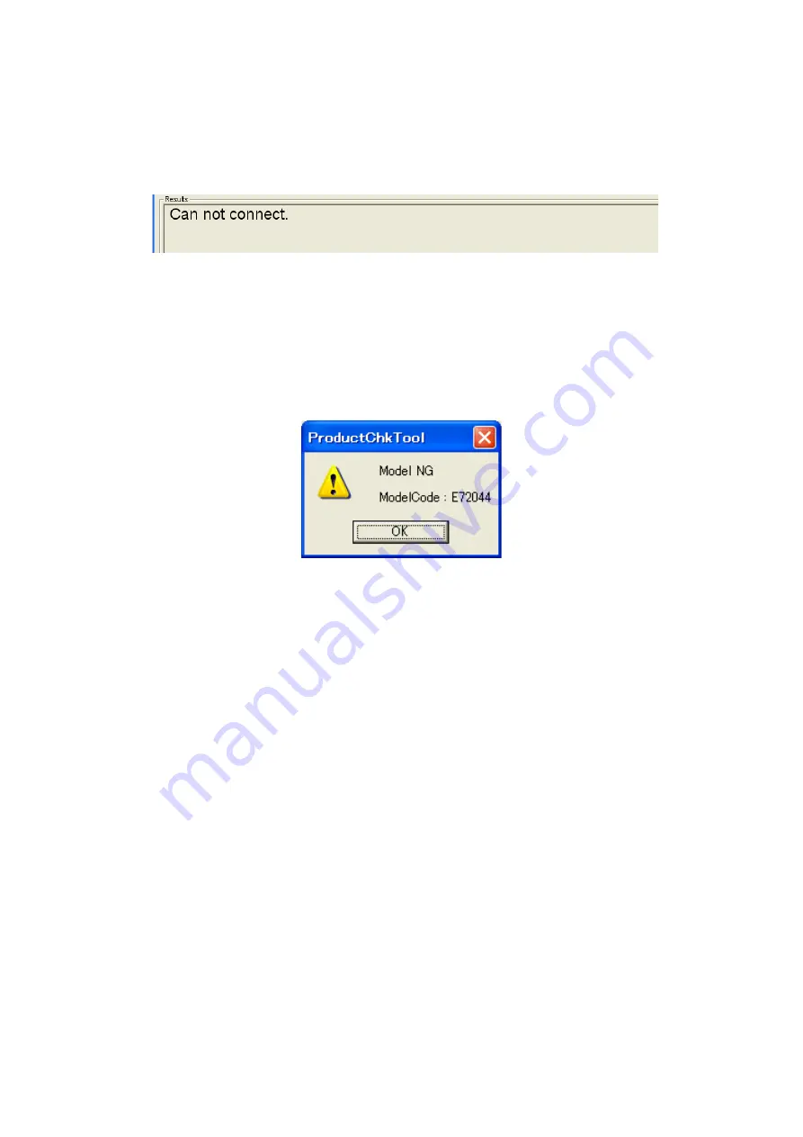
• Model NG

Model code (first 6-digits) of the serial number is not for the relevant model.

The model may be wrong. Check the rating plate to see if it is the right model. Check if 
the tool and inspected model is matched. Version displayed in the "Model Info" field may 
be old. Check if the latest version of the Serviceman tool is being used.

Figure 8. Model NG

Summary of Contents for TD-2020

Page 1: ...SERVICE MANUAL MODEL TD 2020 2120N 2130N ...

Page 2: ...machine is always in best condition for the customer the service personnel must adequately understand and apply this manual This manual is made up of four chapters and appendices CHAPTER I SPECIFICATIONS CHAPTER II THEORY OF OPERATION CHAPTER III DISASSEMBLY AND REASSEMBLY CHAPTER IV TROUBLESHOOTING AND ERROR MESSAGE APPENDIX 1 SERVICEMAN SOFTWARE TOOL Copyright Brother 2013 All rights reserved No...

Page 3: ... 1 3 3 LUBRICATION POINTS LIST III 2 3 4 DISASSEMBLY PROCEDURE III 3 1 Preparation III 3 2 Removing the Bottom Cover B Front Cover and Bottom Cover A III 4 3 Removing the Main PCB ASSY III 7 4 Removing the PCB Holder III 8 5 Removing the Roll Cover ASSY III 10 6 Removing the Roll Sponge L R III 11 7 Removing the Roll Cover Outer A III 12 8 Removing the Roll Cover Front Roll Cover Clear and Roll Co...

Page 4: ...om Cover B III 49 17 Demonstration Print and Final Check III 52 CHAPTER IV TROUBLESHOOTING AND ERROR MESSAGE 4 1 PRECAUTIONS IV 1 4 2 AFTER REPAIRING IV 1 4 3 TROUBLESHOOTING FLOWS IV 2 1 Printing is performed with specific dots omitted IV 2 2 The power supply does not turn ON IV 3 3 No printing is performed IV 4 4 The USB interface malfunction IV 5 5 The Ethernet interface malfunction IV 6 6 The ...

Page 5: ...1 25 1 2 18Check Peel Sensor Paper none 1 26 1 2 19Check Peel Sensor Paper on 1 27 1 2 20Check Battery A D 1 28 1 2 21Check Holder Adaptor AD 1 29 1 2 22Check Battery Charge 1 30 1 2 23Check LED 1 31 1 2 24Write Smart Info 1 33 1 2 25Write Serial No 1 34 1 3 Buffer Analysis Tool 1 37 1 3 1 Role of the Buffer Analysis Tool 1 37 1 3 2 How to start the Buffer Analysis Tool 1 37 1 3 3 Output Buffer Da...

Page 6: ...CIFICATIONS 1 1 MECHANICAL SPECIFICATIONS 1 1 1 External Appearance 1 Dimensions W x D x H 110mm x 215mm x 171 5mm 2 Weight Approx 1340g Printer Figure 1 1 1 External Appearance 215mm 110mm 171 5mm Front side Upper side ...

Page 7: ...ith fixed head and tape feeding 2 Highest printing speed 152 4mm sec 6 ips 3 Print head Type Thick film thermal head TD 2020 2120N 448 dots by one row TD 2130N 672 dots by one row Resolution TD 2020 2120N 203 dpi TD 2130N 300 dpi 1 1 4 Media Specification 1 Types Non coated thermal paper Coated thermal paper Direct thermal die cut labels 1 1 5 Cutter 1 Tape cutting Manual cutting Cutter unit is us...

Page 8: ... PA WI 001 mounted only TD 2120N 2130N 5 USB HOST For barcode reader or for WLAN option 6 Ethernet 10 100 base TX Ethernet only TD 2120N 2130N 1 1 7 Supported OS TD 2020 Microsoft Windows XP Microsoft Windows Vista Microsoft Windows 7 Microsoft Windows 8 TD 2120N 2130N Microsoft Windows XP Microsoft Windows Vista Microsoft Windows 7 Microsoft Windows 8 Microsoft Windows Server 2003 Microsoft Windo...

Page 9: ...IC Xtal 12MHz PCB thermistor Thermal head thermistor Li ion battery Thermal head Stepping motor driver circuit VH VH Main PCB ASSY VH RJ45 connector RS 232C IC RJ25 connector USB host Optional Bluetooth Optional WiFi TD 21xx only USB miniB connector Optional peeler sensor Paper sensor Photo transistor Paper sensor LED Reflective Cover open sensor 5V Optional touch panel display unit Panel PCB swit...

Page 10: ...force comes from a nip between the cylindrical rubber platen and the thermal head At this timing voltage is applied selectively to 448 or 672 pieces of heating elements arrayed on the thermal head By this voltage application the heating elements generate heat and the thermal tape develops dots by itself at heat sensing points After application of voltage the thermal paper is fed to the next printi...

Page 11: ... lifted the lock of the release lever is unlocked so that the roll cover is released The tape can be loaded into the machine in this state When the head ASSY is pressed against the platen roller close the roll cover Figure 2 1 2 Press Contact and Release Mechanism of Thermal Head Head spring Head ASSY Platen roller Release lever Roll cover Release levers Platen roller Head ASSY ...

Page 12: ... against the head ASSY This rotates the tape feed motor ASSY and its drive power is transmitted to the platen gear and the platen roller via the gear train and consequently the platen feeds the tape Figure 2 1 3 Tape Feed Mechanism Tape Head ASSY Platen roller Platen gear Double gear C Double gear A Double gear B Tape feed motor ASSY ...

Page 13: ...or is mounted in the upper cover By closing the roll cover section A of the roll cover inner presses the switch of the cover open sensor and transmits the roll cover closed signal Figure 2 1 4 Cover Open Sensor Roll cover Section A Cover open sensor ...

Page 14: ...t the adjuster lock of the adjuster rack R It allows adjuster rack gears L R to move to left and right To lock the adjuster lock tab to the gear of the upper cover and fix the width release the adjuster lock Figure 2 1 5 Lock and Release of Adjuster Rack Adjuster rack R Upper cover Adjuster lock Tab Adjuster rack L ...

Page 15: ... 0 049 3 5 0 5 PCB holder Taptite bind B M2 6X8 4 0 343 0 049 3 5 0 5 Roll cover outer A Taptite bind B M2 6X8 4 0 343 0 049 3 5 0 5 Roll cover outer B Taptite bind B M2 6X8 4 0 343 0 049 3 5 0 5 Roll cover front Taptite bind B M2 6X8 2 0 343 0 049 3 5 0 5 Roll cover clear Taptite bind B M2 6X8 4 0 343 0 049 3 5 0 5 Panel PCB ASSY Taptite bind B M2 6X8 2 0 343 0 049 3 5 0 5 Tear bar Taptite bind B...

Page 16: ... C Apply Silicon grease G501 4mm size on the shaft Apply Silicon grease G501 4mm size on the two places of the mating teeth surface of the double gear C and the double gear B Apply Silicon grease G501 4mm size on the two places of the mating teeth surface of the double gear B and the double gear A Apply Silicon grease G501 4mm size on the mating teeth surface of the tape feed motor gear and the do...

Page 17: ...button to turn OFF the main power switch 2 Disconnect all cables connected to the machine 3 Lift the release lever to open the roll cover ASSY Remove the thermal tape and close the roll cover ASSY Figure 3 4 1 Thermal tape Roll cover ASSY Release lever Power button ...

Page 18: ...e upside down 2 Remove the four taptite bind B M2 6X6 screws to remove the bottom cover B from the machine 3 Remove the four taptite bind B M2 6X8 screws from the bottom cover A Figure 3 4 2 Bottom cover B Taptite bind B M2 6X6 Taptite bind B M2 6X8 Taptite bind B M2 6X8 Bottom cover A ...

Page 19: ...ase lever to open the roll cover ASSY 6 Remove the two taptite bind B M2 6X8 screws from the front cover Push the bottom cover A outward to remove the front cover Figure 3 4 3 Roll cover ASSY Front cover Taptite bind B M2 6X8 Bottom cover A Release lever ...

Page 20: ...ard to remove it from the machine Remove the guide shaft from the machine and close the roll cover ASSY 8 Remove the four lower foots from the bottom cover A Figure 3 4 4 Roll cover ASSY Bottom cover A Lower foots Guide shaft Lower foots ...

Page 21: ... and the machine 3 Disconnect all harnesses connected to main PCB ASSY 4 Remove the five taptite bind B M2 6X8 screws to remove the main PCB ASSY from the machine 5 Remove the tape B and tape C from the main PCB ASSY Figure 3 4 5 Tape C Tape A Main PCB ASSY Tape B Taptite bind B M2 6X8 Tape A Taptite bind B M2 6X8 ...

Page 22: ... cover ASSY and turn the machine upside down 2 Release each harness from the securing fixture 3 Remove the two taptite bind B M2 6X8 screws Remove the PCB holder from the machine and pull out each harness from the two PCB holder holes Figure 3 4 6 PCB holder Holes Harnesses Taptite bind B M2 6X8 Taptite bind B M2 6X8 Roll cover ASSY Release lever ...

Page 23: ...e left side of the machine is facing downwards Be careful not to lose it 5 Lift the release lever to open the roll cover ASSY 6 Remove the three roll shafts to remove the nine roll rollers from the machine Figure 3 4 7 Roll rollers Roll shafts Release lever Roll cover ASSY ...

Page 24: ...er spring 2 from the damper groove Remove the retaining ring 2 5 and pull out the damper shaft to remove the damper and the damper spring 2 3 Remove the roll cover ASSY from the machine and pull out each harness from the two holes of the machine Figure 3 4 8 Damper shaft Roll cover ASSY Damper shaft Harness Damper spring 2 Retaining rings E2 5 Dampers Damper spring Harness Edge Damper spring 2 Dam...

Page 25: ...III 11 6 Removing the Roll Sponge L R 1 Remove the roll sponge L and roll sponge R from the roll cover inner Figure 3 4 9 Roll sponge R Roll cover inner Roll sponge L ...

Page 26: ... Removing the Roll Cover Outer A 1 Remove the four taptite bind B M2 6X8 screws to remove the roll cover outer A from the roll cover inner Figure 3 4 10 Taptite bind B M2 6X8 Roll cover inner Roll cover outer A ...

Page 27: ... back side of the roll cover inner 2 Remove the six taptite bind B M2 6X8 screws Lift the roll cover outer B to remove the roll cover front and roll cover clear from the roll cover inner Figure 3 4 11 Taptite bind B M2 6X8 Roll cover clear Roll cover inner Taptite bind B M2 6X8 Roll cover outer B Roll cover front Taptite bind B M2 6X8 ...

Page 28: ...o taptite bind B M2 6X8 screws to remove the FG harness ASSY Release the hook to remove the panel PCB ASSY from the roll cover outer B 7 Remove the button A button B status button and two LED lenses from the roll cover outer B Figure 3 4 12 FG harness ASSY Taptite bind B M2 6X8 Panel PCB ASSY Button A Status button LED lenses Roll cover outer B Button B Roll cover inner Hook Filament tape 3M 893 ...

Page 29: ...r bar from the roll cover inner Remove the tear bar cap from the tear bar 2 Turn the release lever ASSY in the direction of the arrow to remove it from the two shaft bushings of the roll cover inner Figure 3 4 13 Taptite bind B M2 6X6 Tear bar cap Shaft bushing Roll cover inner Tear bar Release lever ASSY Shaft bushing ...

Page 30: ...older B and Head Spring 1 Remove the four taptite bind B M2 6X6 screws and remove the head holder B and the two head springs from the roll cover inner Figure 3 4 14 Taptite bind B M2 6X6 Head holder B Roll cover inner Head springs ...

Page 31: ...cover inner Pull out the harness of T sensor PCB ASSY from the hole of the roll cover inner 3 Remove the T sensor PCB ASSY from the sensor holder B 4 Remove the two double face tapes TD2000 from the T sensor PCB ASSY 5 Remove the sensor cover C from the sensor holder B Figure 3 4 15 Sensor cover C Sensor holder B Roll cover inner T sensor PCB ASSY Hole Taptite bind B M2 6X8 Double face tapes TD200...

Page 32: ...ut the two head harnesses and the FG harness ASSY from the two holes of the roll cover inner 2 Disconnect the two head harnesses from the head ASSY 3 Remove the peeler sensor tape from the roll cover inner TD 2120N 2130N models only Figure 3 4 16 Head ASSY Head spring B Roll cover inner FG harness ASSY Head harness Hole Hole Peeler sensor tape TD 2120N 2130N models only Head harness ...

Page 33: ... Cover 1 Remove the four taptite bind B M2 6X8 screws Release the two hooks to remove the upper cover from the mecha ASSY Figure 3 4 17 Upper cover Taptite bind B M2 6X8 Taptite bind B M2 6X8 Taptite bind B M2 6X8 Hooks Mecha ASSY ...

Page 34: ... and the cover open sensor from the upper cover 2 Slide the movable sensor PCB ASSY in the direction of the arrow and remove it by aligning its four tabs to four notches on the upper cover Figure 3 4 18 Tabs Movable sensor PCB ASSY Movable sensor PCB ASSY Cover open sensor SW hold plate Tabs Taptite bind B M2 6X6 Upper cover Upper cover ...

Page 35: ...er from the sensor holder A 3 Remove the RT sensor PCB ASSY from the sensor holder A2 and pull out the harness of the RT sensor PCB ASSY from the hole of the sensor holder A2 4 Push the latch to remove the sensor plate from the sensor holder A2 Figure 3 4 19 Sensor holder A Sensor cover Hook Sensor holder A2 Hook RT sensor PCB ASSY Latch Sensor plate Hole ...

Page 36: ... cup B M2 6X6 screw to remove the adjuster gear from the upper cover 2 Remove the five PStaite M2X4 CH screws to remove the two guide holders from the upper cover Figure 3 4 20 Adjuster gear PStaite M2X4 CH Guide holder Upper cover Taptite cup B M2 6X6 PStaite M2X4 CH Guide holder ...

Page 37: ...k spring from the adjuster rack R while pulling the adjuster lock upward 5 Remove the film spring from the adjuster rack L Secure the roller guide roller firmly and remove the taptite cup B M2 6X6 screw and remove the roller guide roller from the adjuster rack L 6 Remove the film spring 2 from the upper cover Figure 3 4 21 Taptite cup B M2 6X6 Roller guide rollers Adjuster rack L Taptite cup B M2 ...

Page 38: ... platen roller 3 Remove the retaining ring E2 5 to remove the double gear A from the main chassis ASSY 4 Remove the two screw bind M3X4 screws to remove the tape feed motor ASSY from the main chassis ASSY Figure 3 4 22 Platen gear Double gear A Double gear C Hook Double gear B Retaining ring E2 5 Screw bind M3X4 Tape feed motor ASSY Main chassis ASSY Platen roller ...

Page 39: ...sis ASSY 7 Remove the two screw bind M3X4 screws to remove the main chassis R from the sub plate Remove the screw bind M2X3 screw to remove the platen bushing R from the main chassis R 8 Remove the two screw bind M3X4 screws to remove the front cover B from the sub plate Figure 3 4 23 Filament tape Platen bushing L Platen roller Platen bushing R Main chassis R Filament tape Screw bind M2X3 Main ch...

Page 40: ... the screw bind M2X3 screw NOTE When tightening the screw push the platen bushing L in the direction of the arrow B to reduce rattle 5 Insert the platen roller shaft non D cut surface into the platen bushing R 6 Attach the main chassis ASSY to the sub plate with the two screw bind M3X4 screws 7 Stick filament tape W 9mm X L 35 5mm to the main chassis ASSY and main chassis R NOTE Stick the filament...

Page 41: ...ouble gear B to the double gear B shaft on the main chassis ASSY 11 Set the platen gear to the platen roller 12 Set the double gear C to the double gear C shaft on the main chassis ASSY and secure it with the hook Figure 3 5 2 Double gear B shaft Platen roller Double gear C shaft Platen gear Double gear A Double gear C Hook Double gear B Retaining ring E2 5 Screw bind M3X4 Main chassis ASSY Tape f...

Page 42: ...he roller guide roller to the adjuster rack R with the taptite cup B M2 6X6 screw 4 Set the adjuster lock spring in between the bosses of adjuster lock and adjuster rack R Set the adjuster lock to the adjuster rack R and secure it with the two taptite cup B M2 6X6 screws 5 Set the adjuster rack L and the adjuster rack R to the upper cover Figure 3 5 3 Taptite cup B M2 6X6 Roller guide rollers Tapt...

Page 43: ... adjuster rack L and the adjuster rack R outward Attach the adjuster gear to the upper cover with the taptite cup B M2 6X6 screw NOTE Be sure to keep the adjuster rack L and R in engaging position Figure 3 5 4 Adjuster gear PStaite M2X4 CH Guide holder Upper cover Adjuster rack L Taptite cup B M2 6X6 PStaite M2X4 CH Guide holder Adjuster rack R ...

Page 44: ...ge the latch 2 Set the RT sensor PCB ASSY to the sensor holder A2 3 Attach the sensor cover to the sensor holder A 4 Set the sensor holder A to the sensor holder A2 and secure it with the two hooks Figure 3 5 5 Sensor holder A Sensor cover Hook Sensor holder A2 Hook RT sensor PCB ASSY Latch Sensor plate ...

Page 45: ...ite bind B M2 6X6 screw 2 Set four tabs on the movable sensor PCB ASSY to four notches on the upper cover and slide the movable sensor PCB ASSY so that the marking is aligned to the one on the upper cover Figure 3 5 6 Tabs Movable sensor PCB ASSY Markings Movable sensor PCB ASSY Cover open sensor SW hold plate Tabs Taptite bind B M2 6X6 Upper cover Upper cover ...

Page 46: ... Cover 1 Set the upper cover to the mecha ASSY Engage the two hooks and secure them with four taptite bind B M2 6X8 screws Figure 3 5 7 Upper cover Taptite bind B M2 6X8 Taptite bind B M2 6X8 Taptite bind B M2 6X8 Hooks Mecha ASSY ...

Page 47: ...ASSY 3 Insert the two head harnesses and the FG harness ASSY into the two holes on the roll cover inner Set the head spring B in between bosses on the head ASSY and the roll cover inner Set the head ASSY to the roll cover inner while pushing it in the direction of the arrow A and B Figure 3 5 8 Head ASSY Boss Head spring B Roll cover inner Boss A B Head harness ASSY 2 BL FG harness ASSY Hole Hole ...

Page 48: ...holder B using two double face tapes TD2000 3 Insert the T sensor PCB ASSY harness into the hole on the roll cover inner Set the sensor holder B to the roll cover inner and secure it with the two taptite bind B M2 6X8 screws Figure 3 5 9 Sensor cover C Sensor holder B Roll cover inner T sensor PCB ASSY T sensor PCB ASSY Hole Taptite bind B M2 6X8 Double face tapes TD2000 ...

Page 49: ...between the bosses of the head holder B and the head sub plate Set the head holder B to the roll cover inner and secure it with the four taptite bind B M2 6X6 screws Figure 3 5 10 Bosses Taptite bind B M2 6X6 Head holder B Roll cover inner Head springs Bosses of the head sub plate ...

Page 50: ...SSY to the two shaft bushings NOTE Be careful not to scratch roll cover inner with the edge of the release spring 2 Set the tear bar cap to the tear bar Attach the tear bar to the roll cover inner with two taptite bind B M2 6X6 screws Figure 3 5 11 Release spring Taptite bind B M2 6X6 Tear bar cap Shaft bushing Roll cover inner Tear bar Release lever ASSY Edge Shaft bushing ...

Page 51: ...SY to the roll cover outer B and secure it with the hook 3 Secure the panel PCB ASSY and the FG harness ASSY to the roll cover outer B with two taptite bind B M2 6X8 screws NOTE When tightening the screw put the end of FG harness to the hook Figure 3 5 12 FG harness ASSY Taptite bind B M2 6X8 Panel PCB ASSY Button A Status button LED lenses Roll cover outer B Hook Button B FG harness ASSY ...

Page 52: ...l PCB harness and FG harness ASSY with the filament tape 3M 893 W 9mm X L 35 5mm Figure 3 5 13 Hole Roll cover inner Head harness ASSY 1 RD Guide Panel PCB harness Filament tape 3M 893 Panel PCB ASSY Roll cover outer B FG harness ASSY Hole Guide Head harness ASSY 2 BL Sensor cover harness Hook ...

Page 53: ...ver front and the roll cover outer B to the roll cover inner and secure them with six taptite bind B M2 6X8 screws NOTE Use two screws for front side and four screws for back side Figure 3 5 14 Taptite bind B M2 6X8 Roll cover clear Roll cover inner Taptite bind B M2 6X8 Roll cover outer B Roll cover front Taptite bind B M2 6X8 ...

Page 54: ... Attaching the Roll Cover Outer A 1 Set the roll cover outer A to the roll cover inner and secure it with four taptite bind B M2 6X8 screws Figure 3 5 15 Taptite bind B M2 6X8 Roll cover outer A Roll cover inner ...

Page 55: ...III 41 12 Attaching the Roll Sponge L R 1 Stick the roll sponge L and roll sponge R to the roll cover inner Figure 3 5 16 Roll sponge R Roll sponge L Roll cover inner Roll sponge R Roll sponge L ...

Page 56: ...NOTE When assembling the damper push the damper spring outward 3 Align the cut surface and set the damper shaft to the machine Align edge C of the damper spring 2 to the groove of the machine and set it to the damper shaft Align the cut surface to set the damper to the damper shaft and attach the retaining ring E2 5 Engage edge D of the damper spring 2 with the damper groove NOTE When assembling t...

Page 57: ...III 43 14 Attaching the PCB Holder 1 Set the three roll rollers to the roll shaft while inserting it to the machine 3 places Figure 3 5 18 Roll rollers Roll shafts ...

Page 58: ...3 Insert each harness into the two holes of the PCB holder Set the PCB holder to the machine and secure it with two taptite bind B M2 6X8 screws 4 Lift the release lever to open the roll cover ASSY and tighten two taptite bind B M2 6X8 screws from the front side Figure 3 5 19 PCB holder Holes Harnesses Taptite bind B M2 6X8 Taptite bind B M2 6X8 Roll cover ASSY Release lever ...

Page 59: ...III 45 5 Secure each harness with the securing fixture NOTE Be sure to slacken the harness by using round bar as described in the figure below Figure 3 5 20 Slit Harness Harness Slit Round bar ...

Page 60: ... ASSY so that it covers the PCB s edge 2 Stick tape B W 24mm X L 80 5mm to the main PCB ASSY so that it covers the connector foot 3 Attach the main PCB ASSY to the machine with five taptite bind B M2 6X8 screws Figure 3 5 21 Tape B Tape B Main PCB ASSY Tape A Taptite bind B M2 6X8 Tape A ...

Page 61: ...to the machine by sticking two sheets of tape C W 9mm so that the harnesses are blocked in Figure 3 5 22 Tapes C Panel PCB harness Main PCB ASSY Head harness ASSY 1 RD Sensor cover harness Head harness ASSY 2 BL Cover open sensor harness RT sensor harness Tape feed motor harness ...

Page 62: ... bottom cover A 2 Lift the release lever to open the roll cover ASSY 3 Insert the guide shaft into the machine 4 Set the bottom cover A to the machine by pushing it outward NOTE Be careful not to catch the harness Figure 3 5 23 Roll cover ASSY Bottom cover A Lower foots Guide shaft Lower foots Release lever ...

Page 63: ...ont cover to the machine by pushing the bottom cover A outward and secure it with two taptite bind B M2 6X8 screws 6 Close the roll cover ASSY Figure 3 5 24 Roll cover ASSY Front cover Taptite bind B M2 6X8 Bottom cover A ...

Page 64: ...ighten four taptite bind B M2 6X8 screws to the machine 9 Set the bottom cover B to the machine and secure it with four taptite bind B M2 6X6 screws Figure 3 5 25 Bottom cover B Taptite bind B M2 6X6 Taptite bind B M2 6X8 Taptite bind B M2 6X8 ...

Page 65: ... Press and hold the Print button until the POWER indicator starts blinking in green Demonstration print will be printed Figure 3 5 26 Print Sample TD 2020 TD 2120N TD 2130N Total pages printed at the time of the error Error log Total pages printed at the time of the error Error log Total pages printed at the time of the error Error log ...

Page 66: ... is opened and closed properly 6 Confirm that the Feed button works properly 7 Confirm that the Power button works properly 8 You can also check the following printer setting information Program Version Printer Usage History Paper Information Printer Setting Information List of Transferred Data Network Setting Information Error code Error message Description 00 No Error No error Default 01 Check M...

Page 67: ...vice personnel pinpoint and repair other defective elements if he she analyzes and examines them well 4 1 PRECAUTIONS Be sure to observe the following precautions to prevent the secondary problems from happening during troubleshooting 1 Make sure to unplug an DC cord to ensure no power supply when doing conductivity test with a tester 4 2 AFTER REPAIRING Verify again that the repaired portion work...

Page 68: ...e platen are dirty Clean the thermal head and the platen Is the platen rubber deformed Is the head pressure 1 2kgf 5 at the roller center The thermal head is defective Replace the thermal head ASSY Replace the platen ASSY Y N Is the head plate spring attached correctly Attach the head plate spring in correct way Is the head spring attached correctly Attach the head spring in correct way Replace th...

Page 69: ...in PCB ASSY Y N N Are all harnesses connected correctly Correct the connection Y N Is the cable of AC power supply or battery connected correctly Is the main power switch ON Correct the connection Turn ON the main power switch The panel PCB is defective Replace the panel PCB The main PCB is defective Replace the main PCB ...

Page 70: ... print head cable connected correctly If replace the main PCB ASSY is it OK with the print test The thermal head is defective Replace the thermal head ASSY Correct the connection The main PCB is defective Set the roll in the correct direction N Y Is the direction of the roll correctly ...

Page 71: ... Y Y N N The interface malfunction Is the USB cable damaged Is the USB cable connected correctly Is the port set to USB in printer driver property Correct the connection Re install the driver and editor correctly Set to USB port The CPU is defective Replace the main PCB ASSY The USB cable is defective Replace the cable ...

Page 72: ...ce malfunction Is the Ethernet cable damaged Is the Ethernet cable connected correctly Is the port set to Ethernet in printer driver property Correct the connection Re install the driver and editor correctly Set to Ethernet port Except for TD 2020 The CPU is defective Replace the main PCB ASSY The Ethernet cable is defective Replace the cable ...

Page 73: ... Correct the connection Use the interlink cable Re install the driver and editor correctly Set the baud rate correctly Set the system of the flow control of the PC to the Hardware The SATA cable is defective Replace the cable Y N N Is the port set to COM port in printer driver property Y Is the setting including baud rate flow control of printer and PC correct Is the SATA cable damaged Set to COM ...

Page 74: ...ain PCB N Is the Wi Fi BT LED lit in orange Y N Is the slide SW ON Turn it ON Optional component is defective Replace it with a new one N Is the communication restored by rebooting the machine Is it able to detect any signal Is the BT mode selected in printer property Bluetooth only Optional component is defective Replace it with a new one Except for TD 2020 Set to the BT mode Bluetooth only ...

Page 75: ...per the insert guide Is the paper set at the prescribed position Cutter paper guide position Insert the paper correctly Is the head spring attached correctly Attach the head spring correctly Replace the head spring Does the motor rotate Is the motor connected correctly Correct the connection Replace the gears Do the gears rotate The platen is defective Replace the platen Is the motor harness damag...

Page 76: ...e of the connector on the machine side Connect to the machine with no optional products attached and check the performance Even the machine has been equipped with optional products at the time of service you can still operate inspection Item Remark PC Supported OS are Windows XP and Windows 7 A COM port is required USB cable The one included in TD 2000 2100N package or equivalent RS 232C cable D S...

Page 77: ...to check the Wired LAN Wireless LAN and BT communications or other optional products Note that separate inspections are required for each of them as needed This tool supports TD 2020 hereinafter referred to as TD 2000 TD 2120N 2130N hereinafter collectively referred to as TD 2100N Models and the corresponding tools are described in the table below Inspections are inoperable with wrong combination ...

Page 78: ...r Name of inspection Communication I F 2000 2100N Note Read serial no USB O O Check MAC address USB O Write default eeprom data USB O O Write media information USB O O Write product info USB O O Write mass storage info USB O O Write pincode and localname USB O Adjust transmission sensor USB O O Adjust reflecting sensor USB O O Reboot printer USB O O Print test Label USB O O Check adaptor AD USB O ...

Page 79: ...arted simultaneously If the optional battery base unit or optional touch panel display unit is connected with the machine disconnect them before performing inspections Connect the machine to the AC adapter and to the PC with USB cable Turn ON the machine If the Found New Hardware Wizard appears click Cancel The inspection can be done without installing a driver Note Remove the optional battery bas...

Page 80: ...ted inspection press the Down or Up button When all required inspection items are completed click the To next check button to proceed to the next inspection Figure 2 Main window TD 2130N serviceman tool Selected inspection is highlighted in yellow Press here to clear the result and go to the next inspection Press here to start the selected inspection Press here to change the selected inspection ...

Page 81: ...l display unit is attached but the start up screen is not displayed When it happens the machine rejects to receive the inspection command 1 Check if the machine is connected to the AC adapter and to the PC with USB cable 2 Make sure that the Read serial no field is marked in yellow and press the Run button Figure 3 Read serial no start up 3 Enter the serial number 15 digits printed on the rating p...

Page 82: ...tions below The value read is displayed in the Model code and Serial number fields and the corresponding destination is displayed in the Destination field on the main window Conditions for serial number input Tools and model codes for TD 2000 and TD 2100N are matched The serial number entered in the 1st and 2nd fields are the same Figure 6 Serial number field Model Model Code Destination TD 2020 U...

Page 83: ...turned ON Figure 7 Can not connect Model NG Model code first 6 digits of the serial number is not for the relevant model The model may be wrong Check the rating plate to see if it is the right model Check if the tool and inspected model is matched Version displayed in the Model Info field may be old Check if the latest version of the Serviceman tool is being used Figure 8 Model NG ...

Page 84: ... window MAC address also appears in the Results field with a message confirming success Figure 9 MAC address check result Inspection errors Can not connect The following error occurs when the machine is not connected with PC Check that the machine is connected to the PC properly and the machine is turned ON Figure 10 Can not connect The mac address vendor code error The error shown below occurs wh...

Page 85: ...iled error message appears in the Results field and the inspection ends up as NG Note If you want to stop the writing after it s started press the Stop button 1 2 7 Write Media Information Configures default media information data in the machine 1 This inspection starts automatically when the previous inspection is completed When operating this inspection again check that the Write media informati...

Page 86: ...ion again check that the Write product info field is highlighted in yellow then press the Run button Writing result TD 2130N Figure 14 Write product info Write values for each model are shown below Product ID String Model Inspection TD 2000 Valid TD 2100N Valid Model Parameter Write value TD 2020 Product id 2055 Product string TD 2020 TD 2120N Product id 2057 Product string TD 2120N TD 2130N Produ...

Page 87: ... this inspection again check that the Write mass storage info field is highlighted in yellow then press the Run button Writing result TD 2130N Figure 15 Write mass storage info Write values for each model are shown below Product ID String Model Inspection TD 2000 Valid TD 2100N Valid Model Parameter Write value TD 2020 Product id 2059 Product string TD 2020 TD 2120N Product id 205B Product string ...

Page 88: ... the previous inspection is completed When operating this inspection again check that the Write pincode and localname field is highlighted in yellow then press the Run button 2 When the data is successfully written PIN code and local number appears in the Results field on the main window Figure 16 Write pincode and localname Model Inspection TD 2000 Invalid TD 2100N Valid ...

Page 89: ...erly Starting inspection with wrongly positioned sensor would cause shipment of product which is unable to detect media gap Figure 17 Correct position of the sensor 1 Open the cover of the machine to set 80GS OJI roll ASSY to the sensor read section and close the cover Set the roll ASSY so that the gloss surface of the media faces up 2 Make sure that the Adjust transmission sensor field is highlig...

Page 90: ... 4 The adjust photo sensor window appears as soon as the inspection starts Figure 20 Adjust photo sensors window If the cover of the machine is open at that time the Adjust photo sensors window is closed automatically and the inspection ends up as NG Cover check error Cover is open appears in the Results field The inspection is inoperable if the cover of the machine is open at the beginning of the...

Page 91: ... Figure 21 Adjust transmission sensor OK Note A D value and Duty ratio values can be NG even those values are close to OK condition Open the cover and change the position of the 80GS OJI roll ASSY and then try again The result may become OK Conditions required for adjustment OK A D value is within 200 to 205 Duty ratio is within 30 to 100 Possible cause for adjustment NG Photo sensor failure Wrong...

Page 92: ... to the sensor read section and close the cover Set the paper for reflection sensor adjustment so that the peeled area faces up The reflection sensor must be faced to the white part of the paper Do not face it to the black printed part 2 Make sure that the Adjust reflecting sensor field is highlighted in yellow and press the Run button to start the inspection Figure 22 Adjust reflecting sensor sta...

Page 93: ... section and make sure to close the cover 5 When the adjustment is completed the display below appears Once OK appears in the Result field Photo sensor adjust is OK Please open cover appears in the Status field Open the cover When NG appears in the Result field the instruction to open the cover does not appear in the Status field Press the NG button to finish the adjustment Figure 25 Adjust reflec...

Page 94: ...n 162 to 171 Duty ratio is within 30 to 100 Possible cause for adjustment NG Photo sensor failure Wrong or worn out adjustment media The media used are wrong Once OK appears in the Result field open the cover to complete the inspection and adjustment ...

Page 95: ...t the Reboot printer field is highlighted in yellow and press the Run button to start the inspection Figure 26 Reboot printer start up 2 The message below appears in the Results field Please wait for a while until the machine reboots Figure 27 Rebooting message Model Inspection TD 2000 Valid TD 2100N Valid ...

Page 96: ...feeding at the label end and proceed to printing Note When the optional touch panel display unit is connected and template is set in the machine the feeding length would be changed depending on the selected template This may result in wrong feeding position so disconnect the optional touch panel display unit prior to the inspection If the main PCB has been replaced and no template is set optional ...

Page 97: ...20N Figure 30 Printing pattern for 200dpi Printing pattern for 300dpi TD 2130N Figure 31 Printing pattern for 300dpi Reflection sensor stop position Transmission sensor stop position Ejecting direction Reflection sensor stop position Transmission sensor stop position Ejecting direction ...

Page 98: ...art the inspection Figure 32 Check adaptor AD start up Note If the cover of the machine is open at the beginning of the inspection VH Voltage will not be output Close the cover prior to the inspection 2 AD values to be checked appear in the AD field Once all items result in OK the inspection finishes and the window closes automatically Note If any item is not OK press the NG button to finish the i...

Page 99: ...s highlighted in yellow and press the Run button to start the inspection Figure 34 Check USB host start up 2 Check if Detected appears in the Disconnect field when no device is connected to the USB host Figure 35 Disconnection detected 3 Connect the USB bar code reader to the USB host Check that Detected appears in the Connect field Figure 36 USB bar code reader connection detected 4 When Detected...

Page 100: ...a optional touch panel display unit before turning the machine ON 2 Make sure that the Check connect TDU field is highlighted in yellow and press the Run button to start the inspection Figure 37 Check connect TDU start up 3 Once the inspection starts it checks connection between the machine and optional touch panel display unit If they are connected normally it results in OK Figure 38 Check connec...

Page 101: ... sensor Paper none field is highlighted in yellow and press the Run button to start the inspection Figure 40 Check peel sensor Paper none start up 4 When the machine acquires the A D value of the connected optional peeler and the value is met to the OK condition the inspection finishes automatically Note The cover of the machine must be closed If it is open at the time of the inspection close it f...

Page 102: ... start up 3 When the machine acquires the A D value of the connected optional peeler and the value is met to the OK condition the inspection finishes automatically Note The cover of the machine must be closed If it is open at the time of the inspection close it first Note If any item is not OK press the NG button to finish the inspection OK condition Optional peeler A D value paper on is 107 to 25...

Page 103: ... the Check battery AD field is highlighted in yellow and press the Run button to start the inspection Figure 44 Check battery AD start up 3 A D value to be checked appears in the Ad field Once OK appears for all items the inspection finishes automatically Note If any item is not OK press the NG button to finish the inspection Figure 45 Check battery window Conditions required for OK Adaptor State ...

Page 104: ...field is highlighted in yellow and press the Run button to start the inspection Figure 46 Check holder adaptor AD start up 3 A D value to be checked appears in the Ad field Once OK appears for all items the inspection finishes automatically Note If any item is not OK press the NG button to finish the inspection Figure 47 Check battery holder window Conditions required for OK Adaptor State indicate...

Page 105: ...ted in yellow and press the Run button to start the inspection Figure 48 Check battery charge start up 3 Once the message below appears in the Results field the inspection is OK Figure 49 Check battery charge OK Inspection pattern Battery charge is NG The machine is not in the recharging mode Check if the Li ion rechargeable battery is set in the optional battery base unit and the battery does not...

Page 106: ...ton to start the inspection Figure 51 Check LED start up 2 The LED on the machine is lit as LED light pattern 1 shown below If the LED light pattern on the machine and tool is matched press the Feed key on the machine If the LED color is different or does not switch by pressing keys press the NG button on the tool screen to finish the inspection Figure 52 LED light pattern 1 Note When the optional...

Page 107: ... inspection Figure 54 LED light pattern 2 4 By pressing the Print key LED on the machine changes to LED light pattern 3 shown below Again if the LED light pattern on the machine and tool is matched press the OK button on the screen or Enter key on the key board If the LED color is different or does not switch by pressing keys press the NG button on the tool screen to finish the inspection Figure 5...

Page 108: ...0NHC model starts feeding by opening closing the cover Please not that 1 Check that the Write smart info is highlighted in yellow and press the Run button Inspection starts 2 The message below appears in the Results field when the inspection is successfully completed Figure 56 Model Inspection TD 2020 Invalid TD 2120N Invalid TD 2130N Valid ...

Page 109: ...ighlighted in yellow and press the Run button to start the inspection Figure 57 Write serial no start up 3 It starts reading firmware version from the machine and writes serial number into the machine Once the process is completed serial number appears in the Results field on the main screen Figure 58 Write serial no results 4 Check the serial number and press the To next check button Procedures f...

Page 110: ...ection tool settings by following procedures below 1 Start the inspection tool and press the General settings button on the main screen Figure 59 General settings button 2 Press the Setting button in the Target connection field Figure 60 Config window 3 Change the Port No according to the COM port number of the PC to be connected When it is changed press the OK button Figure 61 COM setting ...

Page 111: ...pressed the settings will be remained even after closing the serviceman tool Figure 62 Window prompting to save setting 5 The display automatically returns to the previous Config window Press OK button to return to the main window Figure 63 OK button on Config window COM port setting is completed ...

Page 112: ... buffer analysis tool Tool layout is same as serviceman tool Note Be sure to store all pre included setting files e g ini in the same folder with the execution file ProductCheck exe The tool is inoperable without the file Note Multiple tools cannot be started simultaneously Before implementing any inspection connect the machine to the AC adapter and to the PC with USB cable Turn ON the machine If ...

Page 113: ...nd press the Run button Figure 65 Output buffer data start up 3 The message below appears when the machine is receiving the data Figure 66 Receiving buffer data 4 Once the receiving is completed it requests the binary file name to output As a default the name is in TD2000_YYYYMMDD_hhmmss bin format YYYYMMDD date hhmmss time but it is allowed to change this file name Once the file name is entered p...

Page 114: ...Feb 2013 SM PT056 5 ...

Reviews: