MFC-8220
SERVICE MANUAL
4-41
•
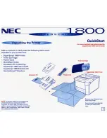
When re-assembling the heat roller 25 to the FU frame upper, ensure you do not damage
the heat roller 25 with the four separate claw ASSY on the FU frame upper.
Fig. 4-73
(18) Remove the pressure roller 25.
Fig. 4-74
Separate claw ASSY
FU frame upper
Separate claw ASSY
Heat roller 25
Pressure roller 25
FU frame lower
FU jam remove cover
2
3
1
Summary of Contents for MFC-8220
Page 60: ...MFC 8220 SERVICE MANUAL 3 5 1 3 4 ROM Fig 3 6 ...
Page 244: ...CHAPTER 7 MAINTENANCE MODE 7 6 Fig 7 2 a b c d e f g h i j ...
Page 312: ...APPENDIX 4 CIRCUIT DIAGRAM A 48 Appendix 4 1 Main PCB Circuit Diagram 1 6 ...
Page 313: ...MFC 8220 SERVICE MANUAL A 49 Appendix 4 2 Main PCB Circuit Diagram 2 6 ...
Page 314: ...APPENDIX 4 CIRCUIT DIAGRAM A 50 Appendix 4 3 Main PCB Circuit Diagram 3 6 ...
Page 315: ...MFC 8220 SERVICE MANUAL A 51 Appendix 4 4 Main PCB Circuit Diagram 4 6 ...
Page 316: ...APPENDIX 4 CIRCUIT DIAGRAM A 52 Appendix 4 5 Main PCB Circuit Diagram 5 6 ...
Page 317: ...MFC 8220 SERVICE MANUAL A 53 Appendix 4 6 Main PCB Circuit Diagram 6 6 ...
Page 318: ...APPENDIX 4 CIRCUIT DIAGRAM A 54 Appendix 4 7 Engine PCB Circuit Diagram 1 2 ...
Page 319: ...MFC 8220 SERVICE MANUAL A 55 Appendix 4 8 Engine PCB Circuit Diagram 2 2 ...
Page 320: ...APPENDIX 4 CIRCUIT DIAGRAM A 56 Appendix 4 9 NCU PCB Circuit Diagram Europe ...
Page 321: ...MFC 8220 SERVICE MANUAL A 57 Appendix 4 10 NCU PCB Circuit Diagram U S A ...
Page 322: ...APPENDIX 4 CIRCUIT DIAGRAM A 58 Appendix 4 11 Control Panel PCB Circuit Diagram ...
Page 323: ...MFC 8220 SERVICE MANUAL A 59 Appendix 4 12 Low voltage Power Supply PCB Circuit Diagram ...
Page 325: ...MFC 8220 SERVICE MANUAL A 61 Appendix 4 14 High voltage Power Supply PCB Circuit Diagram 200V ...
Page 326: ...APPENDIX 4 CIRCUIT DIAGRAM A 62 Appendix 4 15 Back Light PCB Circuit Diagram ...
Page 328: ...February 04 SM FAX026 6 8X5913 Printed in Japan ...